Datasheet 搜索 > RF射频器件 > Microchip(微芯) > ATMEGA1284RFR2-ZF 数据手册 > ATMEGA1284RFR2-ZF 用户编程技术手册 4/607 页

 器件3D模型
¥ 19.525
ATMEGA1284RFR2-ZF 用户编程技术手册 - Microchip(微芯)
制造商:
Microchip(微芯)
分类:
RF射频器件
封装:
VQFN-48
Pictures:
3D模型
符号图
焊盘图
引脚图
产品图
页面导航:
引脚图在P2P5P219P256P274P339Hot
典型应用电路图在P87P179P538
原理图在P3P9P33P46P80P82P85P87P96P192P217P256
型号编码规则在P591P592P593
封装信息在P594
功能描述在P67P361
技术参数、封装参数在P81P95P105P110P550P561P563
应用领域在P1P97P181P207P243P247P485P502P503P538P552
电气规格在P77P180P190P204P205P217P234P235P444P446P550P554

导航目录
ATMEGA1284RFR2-ZF数据手册
Page:
of 607 Go
若手册格式错乱,请下载阅览PDF原文件
4
42073B-MCU Wireless-09/14
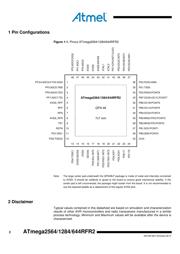
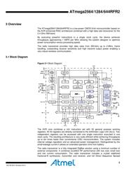
ATmega2564/1284/644RFR2
Spectrum Signal (DSSS) processing with spreading and despreading. The device is
fully compatible with IEEE802.15.4-2011/2006/2003 and ZigBee standards.
The ATmega2564/1284/644RFR2 provides the following features: 256K/128K/64K
Bytes of In-System Programmable (ISP) Flash with read-while-write capabilities,
8K/4K/2K Bytes EEPROM, 32K/16K/8K Bytes SRAM, up to 35 general purpose I/O
lines, 32 general purpose working registers, Real Time Counter (RTC), 6 flexible
Timer/Counters with compare modes and PWM, a 32 bit Timer/Counter, 2 USART, a
byte oriented 2-wire Serial Interface, a 8 channel, 10 bit analog to digital converter
(ADC) with an optional differential input stage with programmable gain, programmable
Watchdog Timer with Internal Oscillator, a SPI serial port, IEEE std. 1149.1 compliant
JTAG test interface, also used for accessing the On-chip Debug system and
programming and 6 software selectable power saving modes.
The Idle mode stops the CPU while allowing the SRAM, Timer/Counters, SPI port, and
interrupt system to continue functioning. The Power-down mode saves the register
contents but freezes the Oscillator, disabling all other chip functions until the next
interrupt or hardware reset. In Power-save mode, the asynchronous timer continues to
run, allowing the user to maintain a timer base while the rest of the device is sleeping.
The ADC Noise Reduction mode stops the CPU and all I/O modules except
asynchronous timer and ADC, to minimize switching noise during ADC conversions. In
Standby mode, the RC oscillator is running while the rest of the device is sleeping. This
allows very fast start-up combined with low power consumption. In Extended Standby
mode, both the main RC oscillator and the asynchronous timer continue to run.
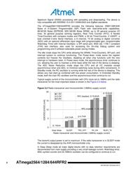
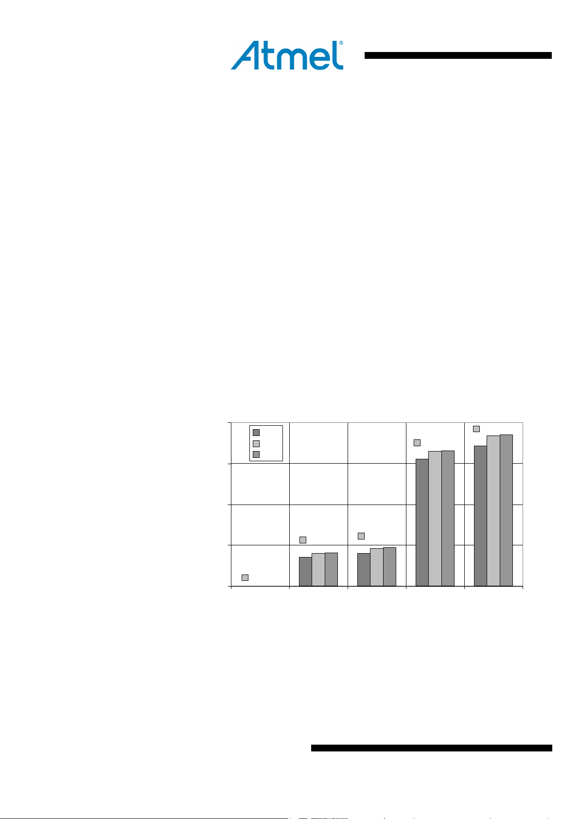
Typical supply current of the microcontroller with CPU clock set to 16MHz and the radio
transceiver for the most important states is shown in the
Figure 3-2 below.
Figure 3-2 Radio transceiver and microcontroller (16MHz) supply current
16,6mA
4,7mA
4,1mA
250nA
18,6mA
0
5
10
15
20
Deep Sleep SLEEP TRX_OFF RX_ON BUSY_TX
Radio transceiver and microcontroller (16MHz) supply current
I(DEVDD,EVDD) [mA]
1.8V
3.0V
3.6V
The transmit output power is set to maximum. If the radio transceiver is in SLEEP mode
the current is dissipated by the AVR microcontroller only.
In Deep Sleep mode all major digital blocks with no data retention requirements are
disconnected from main supply providing a very small leakage current. Watchdog timer,
MAC symbol counter and 32.768kHz oscillator can be configured to continue to run.
700
nA
RPC enabled □ 10.1mA
RPC disabled
器件 Datasheet 文档搜索
AiEMA 数据库涵盖高达 72,405,303 个元件的数据手册,每天更新 5,000 多个 PDF 文件
