Datasheet 搜索 > FPGA芯片 > Microsemi(美高森美) > FLASHPRO5 数据手册 > FLASHPRO5 用户编程技术手册 3/4 页

¥ 385.019
FLASHPRO5 用户编程技术手册 - Microsemi(美高森美)
制造商:
Microsemi(美高森美)
分类:
FPGA芯片
Pictures:
3D模型
符号图
焊盘图
引脚图
产品图
页面导航:
功能描述在P3

导航目录
FLASHPRO5数据手册
Page:
of 4 Go
若手册格式错乱,请下载阅览PDF原文件
Microcontroller
5-33
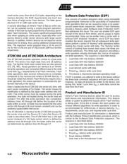
6. Read Address 00001H
Data read is the Device ID Code
7. Load Data AAH into Address 05555H
8. Load Data 55H into Address 02AAAH
9. Load Data F0H into Address 05555H
10. Pause t
WC
(device write cycle time)
11. The device is returned to standard operating mode
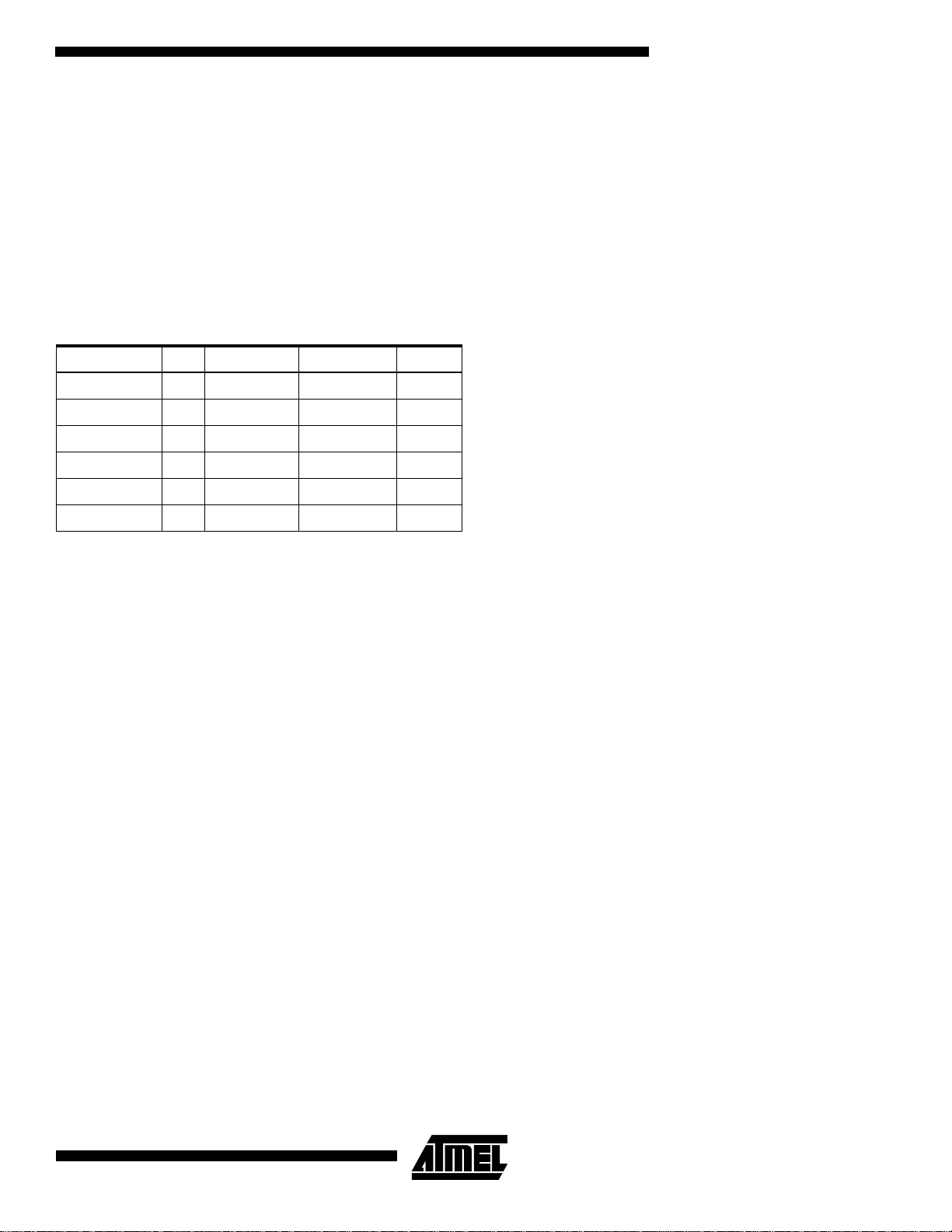
The following table uses the 4M-bit Flash as an example to
illustrate the pertinent device information than can be
determined once the Device ID Code is known.
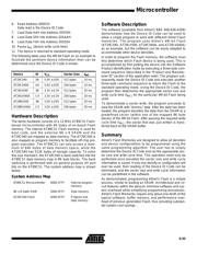
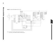
Hardware Description
The demo hardware consists of a 12 MHz AT89C51 Flash-
based microcontroller with 4K bytes of on-board Flash
memory. The internal AT89C51 Flash memory is used for
boot code, and the external 8K x 8 SRAM and the
AT29C040 are mapped as data memory. The AT29C040 is
also mapped as program memory to facilitate off-chip pro-
gram execution. The AT89C51 can only access a maxi-
mum of 64K bytes of data memory space, while the
AT29C040 has 512K bytes of storage capacity. To solve
this size mismatch, the AT29C040 is bank switched into the
AT89C51 data memory map in 8K byte blocks. The bank
switching is performed with six general purpose I/O port
bits on the AT89C51. The system address map is shown
below.
System Address Map
Software Description
The software (available from Atmel’s BBS 408-436-4309)
demonstrates how the Device ID Code can be used to
allow a single program to work with different Atmel Flash
memories. The program uses Atmel’s 4M-bit Flash
(AT29C040, AT29LV040, AT29C040A, and AT29LV040A)
as an example, but the software can be easily adapted to
accommodate other device densities.
In order to program the Flash memory, the software must
first determine which Flash device is being used. This is
accomplished by first putting the device into the Software
Product Identification mode by executing a three-byte com-
mand sequence (described in the “Product and Manufac-
turer ID” section of this application note). The program sub-
sequently reads the Device ID Code and executes another
three-byte command sequence to return the Flash to the
standard operating mode. Using the Device ID Code, the
program then determines the appropriate sector size and
write cycle time (t
WC
)
for the particular 4M-bit Flash being
used.
To demonstrate a sector write, the program proceeds to
load the SRAM with “dummy” data. After the data has been
loaded, the program transfers the data from the SRAM to a
predefined sector (within one of the mapped 8K byte
blocks) of the 4M-bit Flash. After pausing the required write
cycle time (t
WC
),
the sector that was just written is trans-
ferred back to the SRAM buffer.
Summary
Atmel’s Flash Memories are designed to allow all densities
and device configurations to be programmed using the
same programming algorithm. The user has to simply
determine the Device ID Code and set the appropriate sec-
tor size and write cycle time. This operation need only be
performed once provided the sector size and write cycle
information is saved. If only one density or configuration will
ever be used, then reading of the Device ID Code can be
eliminated, and the sector size and write cycle information
can be predefined in the software.
As demonstrated, programming Atmel’s Flash is a simple
process, similar to loading an SRAM. Architectural and cir-
cuit features within the devices minimize software and sys-
tem overhead while simplifying programming procedures.
Atmel’s Flash Memories require only about one-tenth of the
typical software, buffer memory, and performance over-
head of previous generation Flash, thus providing substan-
tial system cost savings.
Device ID V
CC
Sector Size t
WC
AT29C040 5B 5.0V
±
10% 512 bytes 10 ms
AT29C040A A4 5.0V
±
10% 256 bytes 10 ms
AT 29 LV 04 0 3 B 3 .3 V
±
0.3V 512 bytes 20 ms
AT29LV040A C4 3.3V
±
0.3V 256 bytes 20 ms
AT29BV040 3B 3.0V
±
10% 512 bytes 20 ms
AT29BV040A C4 3.0V
±
10% 256 bytes 20 ms
AT89C51 Microcontroller 0000-1FFF Internal program
memory
8K x 8 Static RAM 2000-3FFF Data memory
AT29C040 Flash 4000-5FFF Program and
data memory
器件 Datasheet 文档搜索
AiEMA 数据库涵盖高达 72,405,303 个元件的数据手册,每天更新 5,000 多个 PDF 文件
