Datasheet 搜索 > 微控制器 > Microchip(微芯) > PIC12F1840-E/P 数据手册 > PIC12F1840-E/P 用户编程技术手册 1/38 页
 器件3D模型
¥ 12.032
PIC12F1840-E/P 用户编程技术手册 - Microchip(微芯)
制造商:
Microchip(微芯)
分类:
微控制器
封装:
DIP-8
描述:
PIC12F1822/1840 8 位闪存微控制器Microchip 的 PIC12 微控制器 (MCU) 是世界首个 8 引脚微控制器。 最初已经作为一次可编程 (OTP) 部件推出,此系列设备继续扩展为额外功能且添加了附加改进功能。 PIC12F1822/1840 系列微控制器基于 Microchip 具有深硬件堆栈和 49 个说明的增强型中级芯。 这些 MCU 提供高达 8 MIPS、3.5 K 字节程序内存和 128 字节数据内存。 板载可配置 RC 振荡器,精确度为 ±1%。### 特点49 个指令 16 级硬件堆栈 16 MHz 内部振荡器 – Selectable Output Range from 16 MHz to 31 kHz 6 个输入/输出引脚 1 个比较器 4 通道 10 位模拟至数字转换器 (ADC) 4 通道电容式感应 (mTouch™) 模块 两个 8 位计时器 一个 16 位计时器 1 个增强型捕获、比较 PWM (ECCP) 模块 主同步串行端口 (MSSP),带有 SPI 和 I2C EUSART 在线串行编程 (ICSP) 超低功耗 (XLP) 技术 ### PIC12F 微控制器### Microchip PIC12F 8 位 PIC® 微控制器Microchip 的 PIC12F 微控制器 (MCU) 是世界首个 8 引脚微控制器。 最初已经作为一次可编程 (OTP) 部件推出,此系列的设备将继续扩展为 Microchip 添加额外功能,进一步提高规格,并继续提供比以前更大的值。 PIC12F 成功的关键是在一个 8 引脚封装中允许六个输入/输出通道的内部 RC 振荡器。 此 RC 振荡器的更高版本可在 31kHz 和 32MHz 之间配置。展开
Pictures:
3D模型
符号图
焊盘图
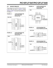
引脚图
产品图
页面导航:
引脚图在P2Hot
技术参数、封装参数在P30
电气规格在P30
导航目录
PIC12F1840-E/P数据手册
Page:
of 38 Go
若手册格式错乱,请下载阅览PDF原文件

2010 Microchip Technology Inc. Advanced Information DS41439A-page 1
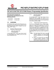
This document includes the
programming specifications for the
following devices:
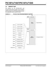
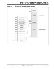
1.0 OVERVIEW
The PIC16F/LF1847 and PIC12F/LF1840 devices can
be programmed using either the high-voltage In-Circuit
Serial Programming™ (ICSP™) method or the low-
voltage ICSP™ method.
1.1 Hardware Requirements
1.1.1 HIGH-VOLTAGE ICSP
PROGRAMMING
In High-Voltage ICSP™ mode, these devices require
two programmable power supplies: one for V
DD and
one for the MCLR
/VPP pin.
1.1.2 LOW-VOLTAGE ICSP
PROGRAMMING
In Low-Voltage ICSP™ mode, these devices can be
programmed using a single V
DD source in the
operating range. The MCLR
/VPP pin does not have to
be brought to a different voltage, but can instead be left
at the normal operating voltage.
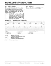
1.1.2.1 Single-Supply ICSP Programming
The LVP bit in Configuration Word 2 enables single-
supply (low-voltage) ICSP programming. The LVP bit
defaults to a ‘1’ (enabled) from the factory. The LVP bit
may only be programmed to ‘0’ by entering the High-
Voltage ICSP mode, where the MCLR
/VPP pin is raised
to V
IHH. Once the LVP bit is programmed to a ‘0’, only
the High-Voltage ICSP mode is available and only the
High-Voltage ICSP mode can be used to program the
device.
• PIC12F1840 • PIC12LF1840
• PIC16F1847 • PIC16LF1847
Note 1: The High-Voltage ICSP mode is always
available, regardless of the state of the
LVP bit, by applying VIHH to the MCLR/
V
PP pin.
2: While in Low-Voltage ICSP mode, MCLR
is always enabled, regardless of the
MCLRE bit, and the port pin can no lon-
ger be used as a general purpose input.
PIC16F/LF1847/PIC12F/LF1840 Memory Programming Specification
PIC16F/LF1847/PIC12F/LF1840
器件 Datasheet 文档搜索
AiEMA 数据库涵盖高达 72,405,303 个元件的数据手册,每天更新 5,000 多个 PDF 文件
