Datasheet 搜索 > 微控制器 > Microchip(微芯) > PIC16F1778T-I/SO 数据手册 > PIC16F1778T-I/SO 用户编程技术手册 5/16 页

 器件3D模型
¥ 6.126
PIC16F1778T-I/SO 用户编程技术手册 - Microchip(微芯)
制造商:
Microchip(微芯)
分类:
微控制器
封装:
SOIC-28
描述:
8位微控制器 -MCU 8-Bit MCU, 28K Flash 2KB RAM, 10b ADC
Pictures:
3D模型
符号图
焊盘图
引脚图
产品图
页面导航:
原理图在P1
应用领域在P10

导航目录
PIC16F1778T-I/SO数据手册
Page:
of 16 Go
若手册格式错乱,请下载阅览PDF原文件
2016 Microchip Technology Inc. DS90003140B-page 5
TB3140
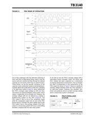
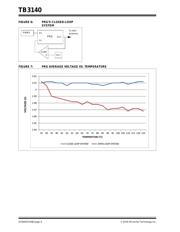
FIGURE 4: PRG MODE OF OPERATION
One of the challenges with the alternate switching of
SW2 and SW3 in Alternating Ramp mode is that the
source and sink currents that flow through the internal
capacitor do not exactly match due to several factors.
These factors can be the parasitic resistance of the
capacitor, noise, production variance and temperature.
It greatly affects the performance of the PRG operating
in an open-loop system (Figure 5), which determines
the PRG’s average output voltage to drift over time.
This event is an inherent limitation of the system, which
makes it impossible to be trimmed out. However, the
average voltage drift can be reduced by creating a
feedback-loop system on the PRG (Figure 6). The
PRG output is tied to one of the comparator inputs
while the comparator output acts as one of the PRG
timing inputs to maintain the peak voltage level of the
PRG output. Hence, the average voltage of the PRG
output in a closed-loop system will have a small drifting
deviation compared with the open-loop system.
To be able to see the PRG’s average voltage drift in
Alternating Ramp Generator mode, the device with
PRG module has been subjected to a continuously
increasing temperature environment. This accelerates
the effect of temperature in the performance of the
PRG output. As shown in Figure 7, there is a significant
average voltage deviation when the PRG operates in
an open-loop system. However, this deviation mini-
mizes and produces almost constant average voltage
when a closed-loop system is employed.
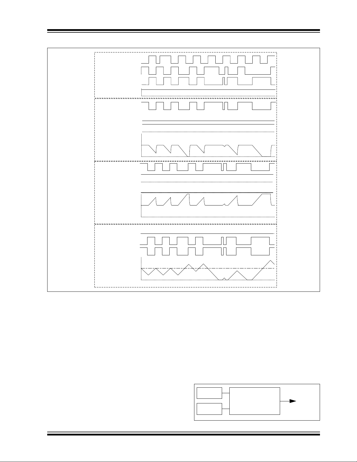
FIGURE 5: PRG’S OPEN-LOOP
SYSTEM
Fall ing Ramp
Generator
MODE<1:0> = 00
2.5V
0V
PRG_out
5V
SW1
OPEN
CLO SE
SW2
SW3
OPEN
CLO SE
OPEN
CLO SE
Rising Ramp
Generator
MODE<1:0> = 10
2.5V
0V
PRG_out
5V
SW1
OPEN
CLO SE
SW2
SW3
OPEN
CLO SE
OPEN
CLO SE
Alternating Ri sing an d
Fall ing Ramp Generator
Mode
MODE<1:0> = 01
2.5V
0V
PRG_out
5V
SW1
OPEN
CLO SE
SW3
OPEN
CLO SE
SW2
CLO SE
OPEN
Input
Sources
R
F
GND
GND
+
+
GND
+
Voltage_ref
0V
2.5V
Q
PWM3
PWM4
PRG
RS
FS
OUT
To other
peripheral
器件 Datasheet 文档搜索
AiEMA 数据库涵盖高达 72,405,303 个元件的数据手册,每天更新 5,000 多个 PDF 文件
