Datasheet 搜索 > 微控制器 > Microchip(微芯) > PIC16F628-20I/P 数据手册 > PIC16F628-20I/P 用户编程技术手册 5/22 页
 器件3D模型
¥ 30.15
PIC16F628-20I/P 用户编程技术手册 - Microchip(微芯)
制造商:
Microchip(微芯)
分类:
微控制器
封装:
PDIP-18
描述:
MICROCHIP PIC16F628-20I/P 微控制器, 8位, 闪存, PIC16F, 20 MHz, 3.5 KB, 224 Byte, 18 引脚, DIP
Pictures:
3D模型
符号图
焊盘图
引脚图
产品图
页面导航:
引脚图在P2Hot

导航目录
PIC16F628-20I/P数据手册
Page:
of 22 Go
若手册格式错乱,请下载阅览PDF原文件
2002 Microchip Technology Inc. Preliminary DS30034D-page 5
PIC16F62X
The optional 16-bit data word will either be an input to,
or an output from the PICmicro
®
MCU, depending on
the command. Load Data commands will be input, and
Read Data commands will be output. The 16-bit data
word only contains 14 bits of data to conform to the 14-
bit program memory word. The 14 bits are centered
within the 16-bit word, padded with a leading and trail-
ing zero.
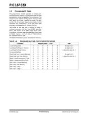
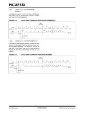
Program/Verify mode may be entered via one of two
methods. High voltage Program/Verify is entered by
holding clock and data pins low while raising V
PP first,
then V
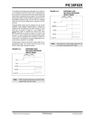
DD, as shown in Figure 2-2. Low voltage Pro-
gram/Verify mode is entered by raising V
DD, then
MCLR
and PGM, as shown in Figure 2-3. The PC will
be set to ‘0’ upon entering into Program/Verify mode.
The PC can be changed by the execution of either an
increment PC command, or a Load Configuration com-
mand, which sets the PC to 0x2000.
All other logic is held in the RESET state while in Pro-
gram/Verify mode. This means that all I/O are in the
RESET state (high impedance inputs).
FIGURE 2-2: ENTERING HIGH
VOLTAGE PROGRAM/
VERIFY MODE
FIGURE 2-3: ENTERING LOW
VOLTAGE PROGRAM/
VERIFY MODE
Note: PGM should be held low to prevent inad-
vertent entry into LVP mode.
VPP
VDD
DATA
CLOCK
Tppdp Thld0
PGM
Note: If the device is in LVP mode, raising VPP to
V
IHH does not override LVP mode.
VDD
MCLR
DATA
CLOCK
Tppdp Thld0
PGM
器件 Datasheet 文档搜索
AiEMA 数据库涵盖高达 72,405,303 个元件的数据手册,每天更新 5,000 多个 PDF 文件
