Datasheet 搜索 > 温度传感器 > TI(德州仪器) > TMP121AIDBVR 数据手册 > TMP121AIDBVR 用户编程技术手册 5/19 页

¥ 17.124
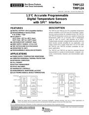
TMP121AIDBVR 用户编程技术手册 - TI(德州仪器)
制造商:
TI(德州仪器)
分类:
温度传感器
封装:
SOT-23-6
描述:
1.5度(-25~+85度)精度SPI接口
Pictures:
3D模型
符号图
焊盘图
引脚图
产品图
页面导航:
导航目录
TMP121AIDBVR数据手册
Page:
of 19 Go
若手册格式错乱,请下载阅览PDF原文件
TMP122, TMP124
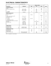
5
SBOS272B
www.ti.com
APPLICATIONS INFORMATION
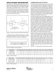
The TMP122 and TMP124 digital temperature sensors are
optimal for thermal management and thermal protection appli-
cations. The TMP122/TMP124 are SPI interface-compatible
and specified for a temperature range of –40°C to +125°C.
The TMP122/TMP124 require minimal external components
for operation, needing only a pull-up resistor on the ALERT
pin and a bypass capacitor on the supply. Bypass capacitors
of 0.1µF is recommended. Figure 1 shows typical connec-
tions for the TMP122 and TMP124.
FIGURE 1. Typical Connections of the TMP122 and TMP124.
COMMUNICATING WITH THE TMP122
The TMP122/TMP124 converts continuously. If
CS
is brought
low during a conversion the conversion process continues, but
the last completed conversion is available at the output regis-
ter. Communication with the TMP122/TMP124 is initiated by
pulling
CS
low. The first 16 clocks of data transfer will return
temperature data from the temperature sensors. The 16-bit
data word is clocked out sign bit first, followed by the MSB. Any
portion of the 16-bit word may be read before raising
CS
. If the
user wishes to continue with
CS
low, the following 16 clocks
transfer in a READ or WRITE command. READ and WRITE
commands are described in Tables I and II.
The READ command contains an embedded address in bits
D4 and D3 to identify which register to read. Bits D4 and D3
are internally registered and will hold their value following a
READ command until a entire 16-bit read is completed by the
user. The completion of the 16-bit READ acknowledges that
the READ command has been completed. If the user issues
a READ command and then raises
CS
with less than 16
subsequent clocks, the data from that register will be available
at the next fall of
CS
. The registered READ address will
remain in effect until a full 16 clocks have been received. After
the completion of a 16-bit READ from the part, the READ
address is reset to return data from the Temperature Register.
A WRITE command to a register will not change the READ
address registered. For further discussion on the READ ad-
dress register, see the
Read Address Register
section.
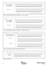
Multiple commands may be strung together as illustrated in
Figure 2. The TMP122/TMP124 accepts commands alternat-
ing with 16-bit response data. On lowering
CS
, the part
always responds with a READ from the address location
indicated by the READ address register. If the next com-
mand is a READ command then data is returned from the
address specified by the READ command with the 16th clock
resetting the READ address register to the default tempera-
ture register. The TMP122/TMP124 then expect a 16-bit
command. If the command is a WRITE command, then the
16 clocks following the command will again return tempera-
ture data.
Figures 3, 4, 5, and 6 detail the communication sequences.
TMP122
0.1µF
V+
GND
2
5
1
3
CS
NOTE: Alert requires
pull-up resistor (open drain).
NC indicates pin should be left
open or floating.
ALERT
(Output)
4
6
SCK
SO/I
TMP124
0.1µF
V+
GND
4
5
7
8
ALERT
(Output)
6
NC
CS
NC
SCK
SO/I
3
1
2
To maintain accuracy in applications requiring air or surface
temperature measurement, care should be taken to isolate
the package and leads from ambient air temperature.
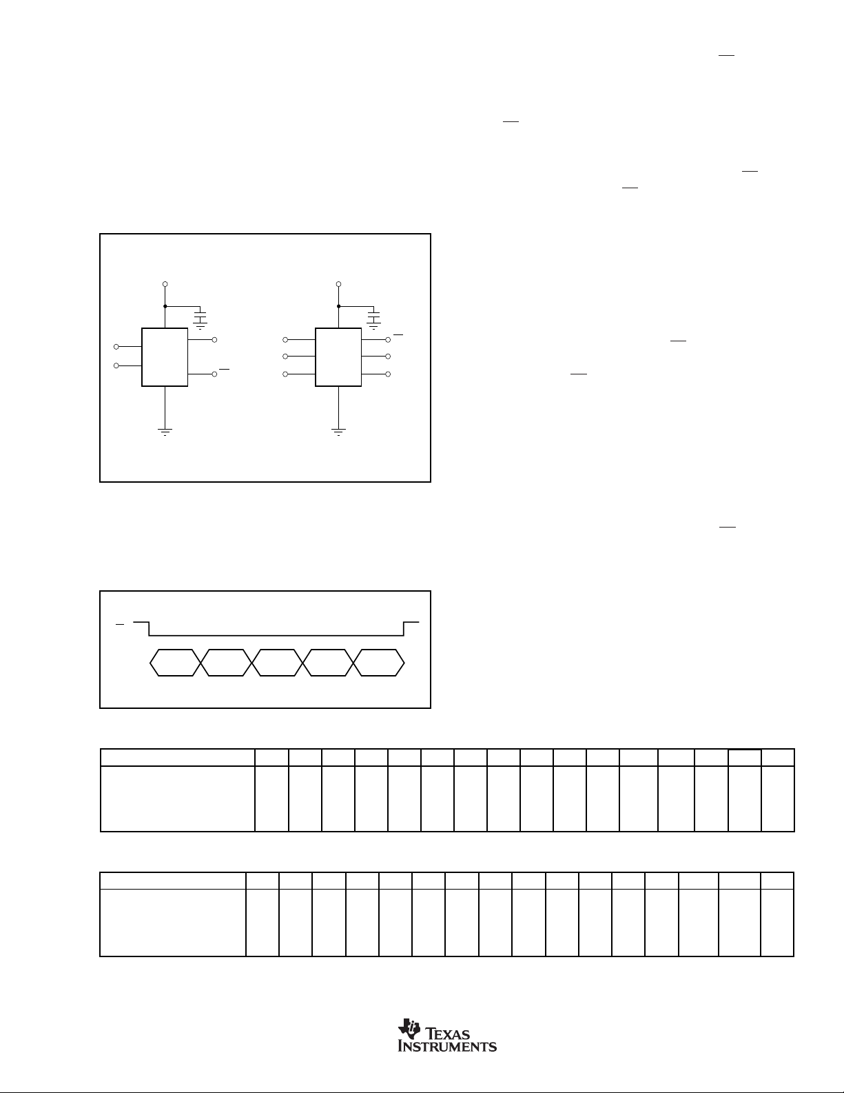
Read Command D15 D14 D13 D12 D11 D10 D9 D8 D7 D6 D5 D4 D3 D2 D1 D0
Temperature 10000000000 0 0000
Configuration Register 10000000000 0 1000
Low Temp Threshold 10000000000 1 0000
High Temp Threshold 10000000000 1 1000
TABLE I. Read Command.
Write Command D15 D14 D13 D12 D11 D10 D9 D8 D7 D6 D5 D4 D3 D2 D1 D0
Configuration Register 0000D1D0R1R0F1F0POLTM1TM00 1 0
Low Temp Threshold T12 T11 T10 T9 T8 T7 T6 T5 T4 T3 T2 T1 T0 1 0 0
High Temp Threshold T12 T11 T10 T9 T8 T7 T6 T5 T4 T3 T2 T1 T0 1 1 0
Shutdown Command xxxxxxxx11111 1 1 1
TABLE II. Write Command.
16-Bit
READ
CS
SO/I
16-Bit
READ
COMMAND
16-Bit
Response
16-Bit
WRITE/
Embedded
Address
16-Bit
READ
FIGURE 2.Multiple Command Sequence.
器件 Datasheet 文档搜索
AiEMA 数据库涵盖高达 72,405,303 个元件的数据手册,每天更新 5,000 多个 PDF 文件
