Datasheet 搜索 > Maxlinear(迈凌) > XRP7724EVB-DEMO-2 数据手册 > XRP7724EVB-DEMO-2 用户编程技术手册 5/19 页


¥ 252.056
XRP7724EVB-DEMO-2 用户编程技术手册 - Maxlinear(迈凌)
制造商:
Maxlinear(迈凌)
描述:
电源管理IC开发工具 Evaluation Board
Pictures:
3D模型
符号图
焊盘图
引脚图
产品图
页面导航:
导航目录
XRP7724EVB-DEMO-2数据手册
Page:
of 19 Go
若手册格式错乱,请下载阅览PDF原文件

X
X
R
R
P
P
7
7
7
7
2
2
4
4
/
/
7
7
7
7
2
2
5
5
E
E
V
V
B
B
-
-
D
D
E
E
M
M
O
O
-
-
2
2
Q
Q
u
u
a
a
d
d
C
C
h
h
a
a
n
n
n
n
e
e
l
l
D
D
i
i
g
g
i
i
t
t
a
a
l
l
P
P
W
W
M
M
/
/
P
P
F
F
M
M
D
D
e
e
m
m
o
o
B
B
o
o
a
a
r
r
d
d
P
P
r
r
o
o
g
g
r
r
a
a
m
m
m
m
a
a
b
b
l
l
e
e
P
P
o
o
w
w
e
e
r
r
M
M
a
a
n
n
a
a
g
g
e
e
m
m
e
e
n
n
t
t
S
S
y
y
s
s
t
t
e
e
m
m
© 2014 Exar Corporation 5/19 Rev. 1.0.0
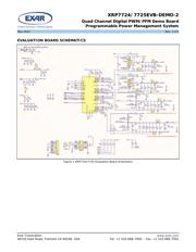
USING THE EVALUATION BOARD
I
NPUT VOLTAGE RANGE
The input voltage range of these boards is
from 5.5V to 25V. The power components
have been optimized for a 12V input rail.
When running the board at an input voltage
other than 12V, use PowerArchitect
TM
5.1 to
evaluate the system performance.
I
2
C INTERFACE
The XRP7724 and XRP7725 programmable
power controllers employ a standard I
2
C
interface. Although the I
2
C signals can be
pulled up to LDO5 on board by means of
installing resistors at the locations R25 and
R26, the I
2
C bus signals are pulled up on the
controller interface board (XR77EVB-INT-1) by
default (refer to Appendix – jumpers installed
shorting pins 2 and 3 together at the locations
JP6 and JP7).
OPERATING THE EVALUATION BOARD
The XRP7724/7725EVB-DEMO-2 is designed to
be powered from either an AC/DC wall wart
(the output voltage must be in the range of
the controllers - 5.5V to 25V) connected to the
barrel connector or a test bench DC power
supply (the voltage must be in the range of
the controllers - 5.5V to 25V) connected to the
V
IN
connectors.
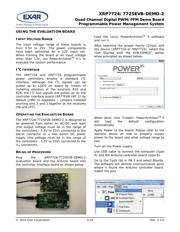
BRING UP PROCEDURE
Plug the XRP7724/7725EVB-DEMO-2
evaluation board and the Arduino board into
the controller interface board as shown below.
Load the
latest PowerArchitect
TM
5 software
and run it.
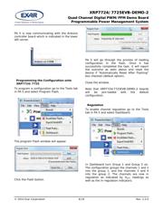
After selecting the proper family (Chips) and
the device (XRP7724 or XRP7725), select the
“Get Started with the EVB-DEMO2” option
when prompted as shown below.
When done, click “Create”. PowerArchitect
TM
5
will load the default configuration
automatically.
Apply Power to the board. Please refer to the
sections above on how to properly supply
power to the board and what voltage range to
use.
Turn on the Power supply.
Use USB cable to connect the computer (type
A) and the Arduino controller board (type B).
Go to the Tools tab in PA 5 and select Boards.
The software will identify communication ports
where it found the Arduino controller board.
Select the port.
器件 Datasheet 文档搜索
AiEMA 数据库涵盖高达 72,405,303 个元件的数据手册,每天更新 5,000 多个 PDF 文件
