Datasheet 搜索 > 微控制器 > ATMEL(爱特美尔) > AT91SAM7S64C-MU 数据手册 > AT91SAM7S64C-MU 开发手册 3/11 页
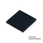
 器件3D模型
¥ 8.436
AT91SAM7S64C-MU 开发手册 - ATMEL(爱特美尔)
制造商:
ATMEL(爱特美尔)
分类:
微控制器
封装:
QFN-64
描述:
AT91 系列 55 MHz 64 kB 闪存 16 kB SRAM 微控制器 - QFN-64
Pictures:
3D模型
符号图
焊盘图
引脚图
产品图
页面导航:
应用领域在P1
导航目录
AT91SAM7S64C-MU数据手册
Page:
of 11 Go
若手册格式错乱,请下载阅览PDF原文件

3
6131A–ATARM–04-Mar-05
AT91 ARM Thumb
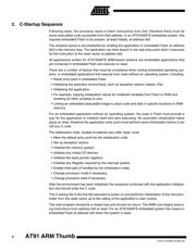
3. C - Startup Example
A generic start-up file is included within this Application Note and others are available in the
AT91 software package. The example described is based on the AT91SAM7S64 Evaluation
Board, C-startup sequence working with IAR V4.11A Development Tool and debugging in
embedded Flash Memory or RAM Memory. This file must be modified in order to fit the needs of
the user application.
The AT91SAM7S64 Evaluation Board is described in the AT91 software package inside the
“compil” subdirectory. Each of these subdirectories contains the following files:
• The board.h file, defines the components of the board in C.
• One Cstartup.s79 file, defines standard boot for the board according to the software
development tools used.
• One Cstartup_xxx.c file, defines standard low level initialization for the board according to the
software development tools used.
The AT91 software package provides C-Startup files that explain how to boot an AT91SAM7S
device and how to branch to the main C function. The C-Startup file takes into account the spe-
cific features of the device, the board specific characteristics and the debug level required.
Note: The software example is delivered “As Is” without warranty or condition of any kind, either express,
implied or statutory. This includes without limitation any warranty or condition with respect to mer-
chantability or fitness for any particular purpose, or against the infringements of intellectual
property rights of others.
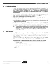
3.1 Area Definition
In an ARM assembly language source file, the start of the module is marked by the PROGRAM
directive, this directive sets the module for the linker. Following this module the second directive
defines the segment named RSEG and the specific segment ICODE that defines C-startup and
exception code area.
At the reset, the ARM core sets ARM Mode and fetches a 32-bit ARM Instruction. The CODE32
directive sets the subsequent instructions to be interpreted as 32-bit ARM Instructions.
An embedded image is placed in embedded Flash at 0x0 by the assembler ORG directive.
;-------------------------------------------------------------------
PROGRAM ?RESET
RSEG ICODE:CODE:ROOT(2)
CODE32 ; Always ARM mode after reset
org 0
reset:
器件 Datasheet 文档搜索
AiEMA 数据库涵盖高达 72,405,303 个元件的数据手册,每天更新 5,000 多个 PDF 文件
