Datasheet 搜索 > 微控制器 > ST Microelectronics(意法半导体) > STM32F102C6T6A 数据手册 > STM32F102C6T6A 开发手册 4/10 页
 器件3D模型
¥ 8.389
STM32F102C6T6A 开发手册 - ST Microelectronics(意法半导体)
制造商:
ST Microelectronics(意法半导体)
分类:
微控制器
封装:
LQFP-48
描述:
STM32F102 系列微处理器,STMicroelectronicsST 的 STM32F102 MCU 系列 ARM Cortex™ M3、32 位 RISC 内核运行频率高达 48MHz,带高达 128 KB 的高速闪存、高达 16 KB 的 SRAM 以及增强型外设。 ARM™ 处理器 STM32 F102 32 位微控制器具有一个通信接口;计时器;ADC 和 DAC。 STM32 系列 ARM Cortex-M3 32 位闪存产品系列以低功率、低电压运行,并结合了带实时功能的高性能,可以在 STMicroelectronics STM32 平台上运行。 微控制器可用于如应用控制、消费者电器用具、PC 外设、手持设备、HVAC 及其他许多应用领域。 48 MHz CPU,带 USB FS 电源:2 V 至 3.6 V 通信接口:I2C、SPI、USART 12 位 ADC;16 位计时器 温度范围:-40 至 +85 °C ### STM32F1 系列 32 位 ARM® Cortex®-M3 微控制器,STMicroelectronics32 位闪存微控制器的 STM32 系列基于 ARM Cortex™ M3 核心的突破 - 为嵌入式应用特别开发的核心。 STM32 系列得益于 Cortex-M3 体系结构增强功能,包括为传达改进性能而设置的 Thumb-2 指令,带更好的编码密度,对中断更快的反应,所有的均和领先的工业功耗相接合。出色的实时表现 卓越功效 卓越的和新型的外围设备 最大程度的集成 跨族引脚,外围设备和软件兼容性展开
Pictures:
3D模型
符号图
焊盘图
引脚图
产品图
页面导航:
应用领域在P10


导航目录
STM32F102C6T6A数据手册
Page:
of 10 Go
若手册格式错乱,请下载阅览PDF原文件
FIFO emulation with DMA AN3109
4/10 Doc ID 16795 Rev 1
1 FIFO emulation with DMA
1.1 FIFO overview
FIFO is an acronym for first in, first out. It is an abstraction of the ways of organizing and
manipulating data in terms of time and order. This expression describes a queue-processing
technique. It consists in the servicing of conflicting demands based on the principle of first-
come, first-served: the data that come in first are handled first, the data that come in next
are served after the first data in are removed, etc.
FIFO (first in first out) requires that the first data item input is the first output. It is necessary
to keep track of the amount of data items in the buffer so that data are not dropped or
duplicated.
A circular buffer is an efficient way of implementing a FIFO. Figure 1 shows an 8-byte
circular buffer.
Figure 1. Circular buffer diagram
This buffer has 8 bytes of storage. It is referred to as circular because the next position
accessed after position 7 is position 0.
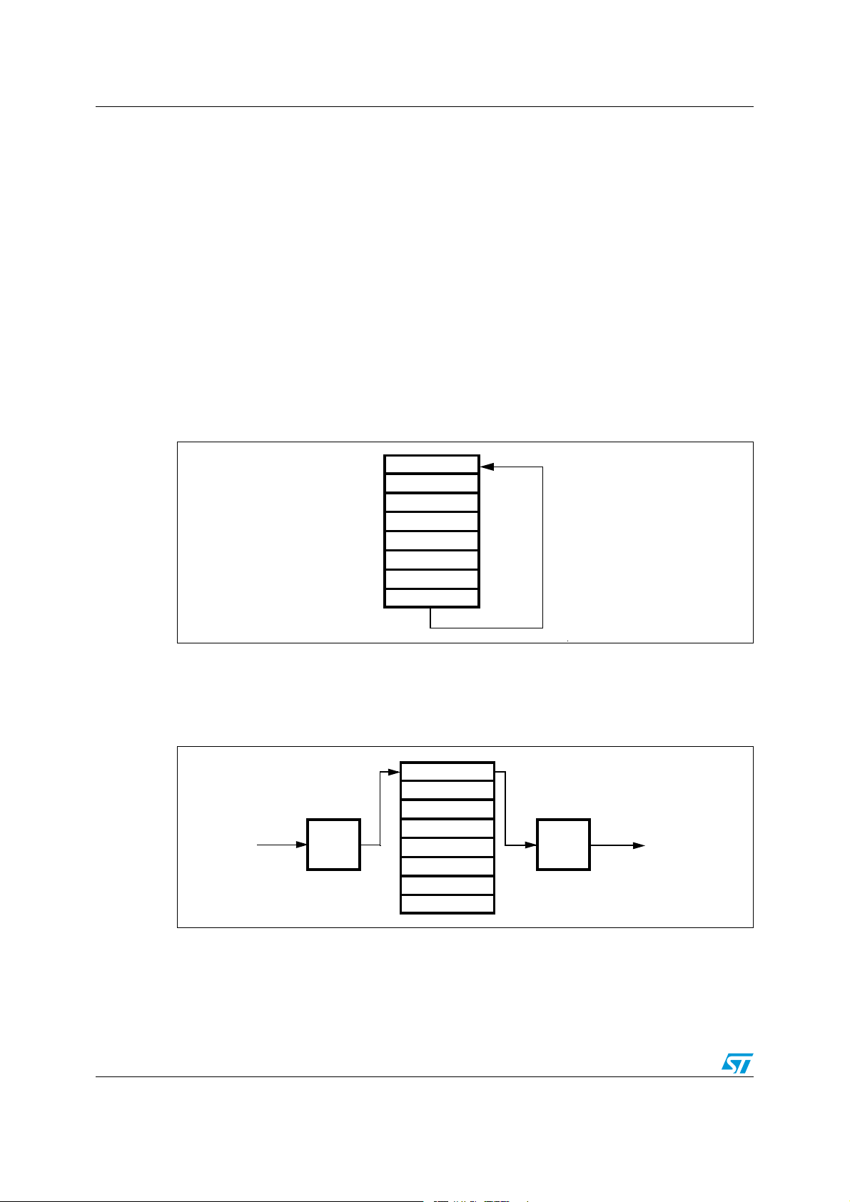
Figure 2 shows two pointers used to control the movement of data into and out of the buffer.
Figure 2. Circular buffer pointer diagram
The write pointer points to the next available buffer location to be written. It is incremented
when data are placed into the buffer. The read pointer points to the next buffer location to be
read. It is incremented when data are fetched from the buffer.
AI
$ATAIN
$ATAOUT
7RITE
BUFFER
POINTER
2EAD
BUFFER
POINTER
AI
器件 Datasheet 文档搜索
AiEMA 数据库涵盖高达 72,405,303 个元件的数据手册,每天更新 5,000 多个 PDF 文件
