Datasheet 搜索 > 微控制器 > Microchip(微芯) > AT89C51RD2-SLSUM 数据手册 > AT89C51RD2-SLSUM 其他数据使用手册 6/7 页
 器件3D模型
¥ 54.053
AT89C51RD2-SLSUM 其他数据使用手册 - Microchip(微芯)
制造商:
Microchip(微芯)
分类:
微控制器
封装:
PLCC-44
描述:
AT89C51 系列 60 MHz 64 KB 闪存 2 KB SRAM 8 位 微控制器 - PLCC-44
Pictures:
3D模型
符号图
焊盘图
引脚图
产品图
页面导航:
型号编码规则在P7
技术参数、封装参数在P2


导航目录
AT89C51RD2-SLSUM数据手册
Page:
of 7 Go
若手册格式错乱,请下载阅览PDF原文件
FE-51RD2 - Page 6
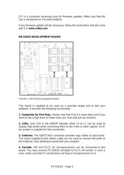
5. Power Switch. The power switch is on the left side of the board. It has
three positions: OFF, 3.3V and 5V. Although the input voltage is always 5V,
the system has a built-in voltage regulator (U5) that drops the voltage to 3.3V
if the switch is set accordingly. Use the power supply included in the system
and connect it to the Power In jack (J8).
6. Potentiometer. This 50KOhm potentiometer is used to get on TP1 analog
input from 0 to Vcc (which is 3.3V or 5V according to the power switch
position).
7. ISP Connector. J7 is an ISP connector that can be used directly with MP-
51RD2 programmer to program the microcontroller installed on the 40-DIP or
44-PLCC socket. A 10-pin ribbon cable is supplied for this purpose.
8. Oscillator Options. This board can be used to connect a full size crystal
oscillator (16-DIP), half size (8-DIP) or a 2-pin crystal with capacitors as
shown on the board.
9. Future Options. The board is prepared to be used with future derivatives,
which have pin signals not supported by the 89C51RD2 and as shown on J9
connector. Additional frequency options for new derivatives are prepared with
C1, C2 and Y1 crystal placements.
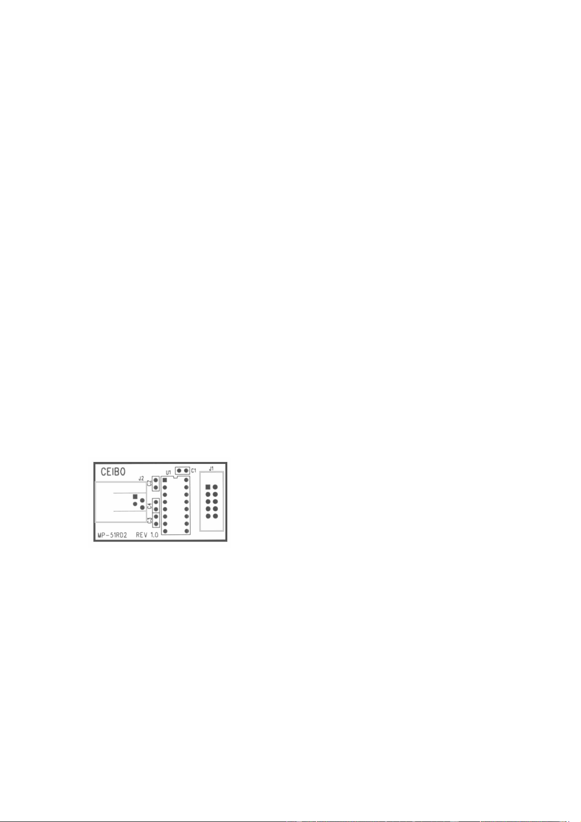
MP-51RD2 PROGRAMMER
This small board contain the RS-232 interface to ISP signals. Use it together
with the supplied 10-pin ribbon cable and the software driver available from
Atmel W&M website.
FIGURE 3: MP-51RD2 Programmer
器件 Datasheet 文档搜索
AiEMA 数据库涵盖高达 72,405,303 个元件的数据手册,每天更新 5,000 多个 PDF 文件
