Datasheet 搜索 > 微控制器 > ATMEL(爱特美尔) > AT91SAM9263B-CU-100 数据手册 > AT91SAM9263B-CU-100 其他数据使用手册 2/23 页
 器件3D模型
¥ 7.191
AT91SAM9263B-CU-100 其他数据使用手册 - ATMEL(爱特美尔)
制造商:
ATMEL(爱特美尔)
分类:
微控制器
封装:
TFBGA-324
描述:
SMART SAM9G ARM® 9 微处理器基于 ARM926™ 的 Atmel® SMART SAM9G 嵌入式微处理器单元 (MPU) 是高性能数据速度处理器,带扩展外围设备,用于连接和用户界面。### ARM 微控制器,Atmel
Pictures:
3D模型
符号图
焊盘图
引脚图
产品图
页面导航:
应用领域在P3

导航目录
AT91SAM9263B-CU-100数据手册
Page:
of 23 Go
若手册格式错乱,请下载阅览PDF原文件

2
6299A–ATARM–27-Mar-07
Application Note
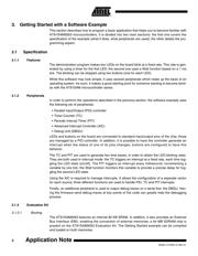
3. Getting Started with a Software Example
This section describes how to program a basic application that helps you to become familiar with
AT91SAM9263 microcontrollers. It is divided into two main sections: the first one covers the
specification of the example (what it does, what peripherals are used); the other details the pro-
gramming aspect.
3.1 Specification
3.1.1 Features
The demonstration program makes two LEDs on the board blink at a fixed rate. This rate is gen-
erated by using a timer for the first LED; the second one uses a Wait function based on a 1 ms
tick. The blinking can be stopped using two buttons (one for each LED).
While this software may look simple, it uses several peripherals which make up the basis of an
operating system. As such, it makes a good starting point for someone wanting to become famil-
iar with the AT91SAM microcontroller series.
3.1.2 Peripherals
In order to perform the operations described in the previous section, the software example uses
the following set of peripherals:
• Parallel Input/Output (PIO) controller
• Timer Counter (TC)
• Periodic Interval Timer (PIT)
• Advanced Interrupt Controller (AIC)
• Debug Unit (DBGU)
LEDs and buttons on the board are connected to standard input/output pins of the chip; those
are managed by a PIO controller. In addition, it is possible to have the controller generate an
interrupt when the status of one of its pins changes; buttons are configured to have this
behavior.
The TC and PIT are used to generate two time bases, in order to obtain the LED blinking rates.
They are both used in interrupt mode: the TC triggers an interrupt at a fixed rate, each time tog-
gling the LED state (on/off). The PIT triggers an interrupt every millisecond, incrementing a
variable by one tick; the Wait function monitors this variable to provide a precise delay for tog-
gling the second LED state.
Using the AIC is required to manage interrupts. It allows the configuration of a separate vector
for each source; three different functions are used to handle PIO, TC and PIT interrupts.
Finally, an additional peripheral is used to output debug traces on a serial line: the DBGU. Hav-
ing the firmware send debug traces at key points of the code can greatly help the debugging
process.
3.1.3 Evaluation Kit
3.1.3.1 Booting
The AT91SAM9263 features an internal 80 KB SRAM. In addition, it also provides an External
Bus Interface (EBI), enabling the connection of external memories; a 64 MB SDRAM chip is
present on the AT91SAM9263 Evaluation Kit. The Getting Started example can be compiled
and loaded on both memories.
器件 Datasheet 文档搜索
AiEMA 数据库涵盖高达 72,405,303 个元件的数据手册,每天更新 5,000 多个 PDF 文件
