Datasheet 搜索 > 微控制器 > ATMEL(爱特美尔) > AT91SAM9263B-CU-100 数据手册 > AT91SAM9263B-CU-100 其他数据使用手册 4/23 页
 器件3D模型
¥ 7.19
AT91SAM9263B-CU-100 其他数据使用手册 - ATMEL(爱特美尔)
制造商:
ATMEL(爱特美尔)
分类:
微控制器
封装:
TFBGA-324
描述:
SMART SAM9G ARM® 9 微处理器基于 ARM926™ 的 Atmel® SMART SAM9G 嵌入式微处理器单元 (MPU) 是高性能数据速度处理器,带扩展外围设备,用于连接和用户界面。### ARM 微控制器,Atmel
Pictures:
3D模型
符号图
焊盘图
引脚图
产品图
页面导航:
应用领域在P3
导航目录
AT91SAM9263B-CU-100数据手册
Page:
of 23 Go
若手册格式错乱,请下载阅览PDF原文件

4
6299A–ATARM–27-Mar-07
Application Note
ldr pc, =reset_handler
undef_vector:
b undef_vector /* Undefined Instruction */
swi_vector:
b swi_vector /* Software Interrupt */
pabt_vector:
ldr pc, =pabt_handler /* Prefetch Abort */
dabt_vector:
ldr pc, =dabt_handler /* Data Abort */
rsvd_vector:
b rsvd_vector /* reserved */
irq_vector:
b irq_handler /* IRQ : read the AIC */
fiq_vector:
b fiq_vector /* FIQ */
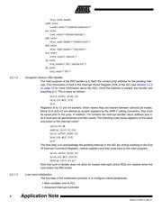
3.2.1.2 Exception Vectors: IRQ Handler
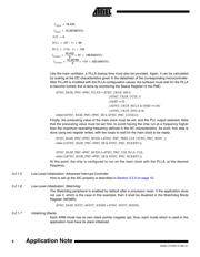
The main purpose of the IRQ handler is to fetch the correct jump address for the pending inter-
rupt. This information is held in the Interrupt Vector Register (IVR) of the AIC (see Section 3.2.3
on page 10 for more information about the AIC). Once the address is loaded, the handler just
branches to it. This is done as follows:
ldr r14, =AT91C_BASE_AIC
ldr r0, [r14, #AIC_IVR]
bx r0
Registers r0 to 12 are not banked, which means they are shared between (almost) all modes.
Since r0-r3 and r12 are defined as scratch registers by the ARM C calling convention, they must
be saved prior to the jump. In addition, r14 contains the interrupt handler return address plus 4,
so it must also be decremented and then saved. The following code saves registers on the stack
and jumps to the interrupt vector:
sub r14, r14, #4
stmfd sp!, {r0-r3, r12, r14}
ldr r14, =AT91C_BASE_AIC
ldr r0, [r14, #AIC_IVR]
bx r0
The final step is to acknowledge the pending interrupt in the AIC (by writing anything in the End
Of Interrupt Command Register), restore registers and then jump back to the main program:
ldr r14, =AT91C_BASE_AIC
str r14, [r14, #AIC_EOICR]
ldmfd sp!, {r0-r3, r12, pc}^
Note that such a handler does not allow for nested interrupts (since IRQs are masked when the
core enters the IRQ mode).
3.2.1.3 Low-Level Initialization
The first step of the initialization process is to configure critical peripherals:
• Main oscillator and its PLL
• Advanced Interrupt Controller
器件 Datasheet 文档搜索
AiEMA 数据库涵盖高达 72,405,303 个元件的数据手册,每天更新 5,000 多个 PDF 文件

