Datasheet 搜索 > 微控制器 > ATMEL(爱特美尔) > AT91SAM9263B-CU-100 数据手册 > AT91SAM9263B-CU-100 其他数据使用手册 6/23 页

 器件3D模型
¥ 7.182
AT91SAM9263B-CU-100 其他数据使用手册 - ATMEL(爱特美尔)
制造商:
ATMEL(爱特美尔)
分类:
微控制器
封装:
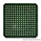
TFBGA-324
描述:
SMART SAM9G ARM® 9 微处理器基于 ARM926™ 的 Atmel® SMART SAM9G 嵌入式微处理器单元 (MPU) 是高性能数据速度处理器,带扩展外围设备,用于连接和用户界面。### ARM 微控制器,Atmel
Pictures:
3D模型
符号图
焊盘图
引脚图
产品图
页面导航:
应用领域在P3
导航目录
AT91SAM9263B-CU-100数据手册
Page:
of 23 Go
若手册格式错乱,请下载阅览PDF原文件

6
6299A–ATARM–27-Mar-07
Application Note
Like the main oscillator, a PLLA startup time must also be provided. Again, it can be calculated
by looking at the DC characteristics given in the datasheet of the corresponding microcontroller.
After PLLAR is modified with the PLLA configuration values, the software must wait for the PLLA
to become locked; this is done by monitoring the Status Register of the PMC.
AT91C_BASE_PMC->PMC_PLLAR = AT91C_CKGR_SRCA
| AT91C_CKGR_OUTA_0
| (0xBF << 8)
| (AT91C_CKGR_MULA & (0x6D << 16))
| (AT91C_CKGR_DIVA & 9);
while(!(AT91C_BASE_PMC->PMC_SR & AT91C_PMC_LOCKA));
Finally, the prescaling value of the main clock must be set, and the PLL output selected. Note
that the prescaling value must be set first, to avoid having the chip run at a frequency higher
than the maximum operating frequency defined in the AC characteristics. As such, this step is
done using two register writes, with two loops to wait for the main clock to be ready:
AT91C_BASE_PMC->PMC_MCKR = AT91C_PMC_PRES_CLK | AT91C_PMC_MDIV_2;
while (!(AT91C_BASE_PMC->PMC_SR & AT91C_PMC_MCKRDY));
AT91C_BASE_PMC->PMC_MCKR |= AT91C_PMC_CSS_PLLA_CLK;
while (!(AT91C_BASE_PMC->PMC_SR & AT91C_PMC_MCKRDY));
At this point, the chip is configured to run on the main clock with the PLLA, at the desired
frequency.
3.2.1.5 Low-Level Initialization: Advanced Interrupt Controller
How to set up the AIC properly is described in Section 3.2.3 on page 10.
3.2.1.6 Low-Level Initialization: Watchdog
The Watchdog peripheral is enabled by default after a processor reset. If the application does
not use it, which is the case in this example, then it shall be disabled in the Watchdog Mode
Register (WDMR):
AT91C_BASE_WDTC->WDTC_WDMR = AT91C_WDTC_WDDIS;
3.2.1.7 Initializing Stacks
Each ARM mode has its own stack pointer (register sp); thus, each mode which is used in the
application must have its stack initialized.
f
Input
18.432=
f
Input
16.36766MHz=
DIV 9=
MUL 97 1–()96==
MUL 110 1–()109==
f
Output
18.432
9
------------------
97× 198.656MHz==
f
Output
16.36766
9
-------------------------
110× 200.049MHz==
器件 Datasheet 文档搜索
AiEMA 数据库涵盖高达 72,405,303 个元件的数据手册,每天更新 5,000 多个 PDF 文件


