Datasheet 搜索 > 稳压芯片 > National Semiconductor(美国国家半导体) > LMC7660IMX 数据手册 > LMC7660IMX 产品手册 4/12 页

 器件3D模型
¥ 2.846
LMC7660IMX 产品手册 - National Semiconductor(美国国家半导体)
制造商:
National Semiconductor(美国国家半导体)
分类:
稳压芯片
封装:
PDIP
描述:
LMC7660IMX
Pictures:
3D模型
符号图
焊盘图
引脚图
产品图
页面导航:
导航目录
LMC7660IMX数据手册
Page:
of 12 Go
若手册格式错乱,请下载阅览PDF原文件
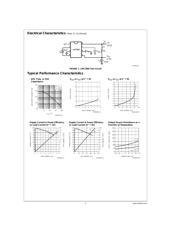
Typical Performance Characteristics (Continued)
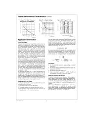
Application Information
Circuit Description
The LMC7660 contains four large CMOS switches which are
switched in a sequence to provide supply inversion V
out
=
−V
in
. Energy transfer and storage are provided by two inex-
pensive electrolytic capacitors.
Figure 2
shows how the
LMC7660 can be used to generate −V
+
from V
+
. When
switches S1 and S3 are closed, C
p
charges to the supply
voltage V
+
. During this time interval, switches S2 and S4 are
open.After C
p
charges to V
+
, S1 and S3 are opened, S2 and
S4 are then closed. By connecting S2 to ground, C
p
devel-
ops a voltage −V
+
/2 on C
r
.After a number of cycles C
r
will be
pumped to exactly −V
+
. This transfer will be exact assuming
no load on C
r
, and no loss in the switches.
In the circuit of
Figure 2
, S1 is a P-channel device and S2,
S3, and S4 are N-channel devices. Because the output is bi-
ased below ground, it is important that the p
−
wells of S3 and
S4 never become forward biased with respect to either their
sources or drains. A substrate logic circuit guarantees that
these p
−
wells are always held at the proper voltage. Under
all conditions S4 p
−
well must be at the lowest potential in the
circuit. To switch off S4, a level translator generates V
GS4
=
0V, and this is accomplished by biasing the level translator
from the S4 p
−
well.
An internal RC oscillator and
÷
2 circuit provide timing sig-
nals to the level translator. The built-in regulator biases the
oscillator and divider to reduce power dissipation on high
supply voltage. The regulator becomes active at about V
+
=
6.5V. Low voltage operation can be improved if the LV pin is
shorted to ground for V
+
≤ 3.5V. For V
+
≥ 3.5V, the LV pin
must be left open to prevent damage to the part.
Power Efficiency and Ripple
It is theoretically possible to approach 100
%
efficiency if the
following conditions are met:
1. The drive circuitry consumes little power.
2. The power switches are matched and have low R
on
.
3. The impedance of the reservoir and pump capacitors are
negligibly small at the pumping frequency.
The LMC7660 closely approaches 1 and 2 above. By using
a large pump capacitor C
p
, the charge removed while sup-
plying the reservoir capacitor is small compared to C
p
’s total
charge. Small removed charge means small changes in the
pump capacitor voltage, and thus small energy loss and high
efficiency. The energy loss by C
p
is:
By using a large reservoir capacitor, the output ripple can be
reduced to an acceptable level. For example, if the load cur-
rent is 5 mA and the accepted ripple is 200 mV, then the res-
ervoir capacitor can omit approximately be calculated from:
Precautions
1. Do not exceed the maximum supply voltage or junction
temperature.
2. Do not short pin 6 (LV terminal) to ground for supply volt-
ages greater than 3.5V.
3. Do not short circuit the output to V
+
.
4. External electrolytic capacitors C
r
and C
p
should have
their polarities connected as shown in
Figure 1
.
Replacing Previous 7660 Designs
To prevent destructive latchup, previous 7660 designs re-
quire a diode in series with the output when operated at el-
evated temperature or supply voltage. Although this pre-
vented the latchup problem of these designs, it lowered the
available output voltage and increased the output series re-
sistance.
The National LMC7660 has been designed to solve the in-
herent latch problem. The LCM7660 can operate over the
entire supply voltage and temperature range without the
need for an output diode. When replacing existing designs,
the LMC7660 can be operated with diode Dx.
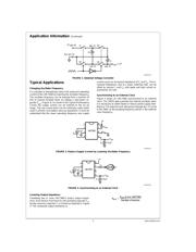
Unloaded Oscillator Frequency
as a Function of Temperature
DS009136-24
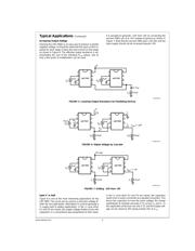
Output R vs Supply Voltage
DS009136-25
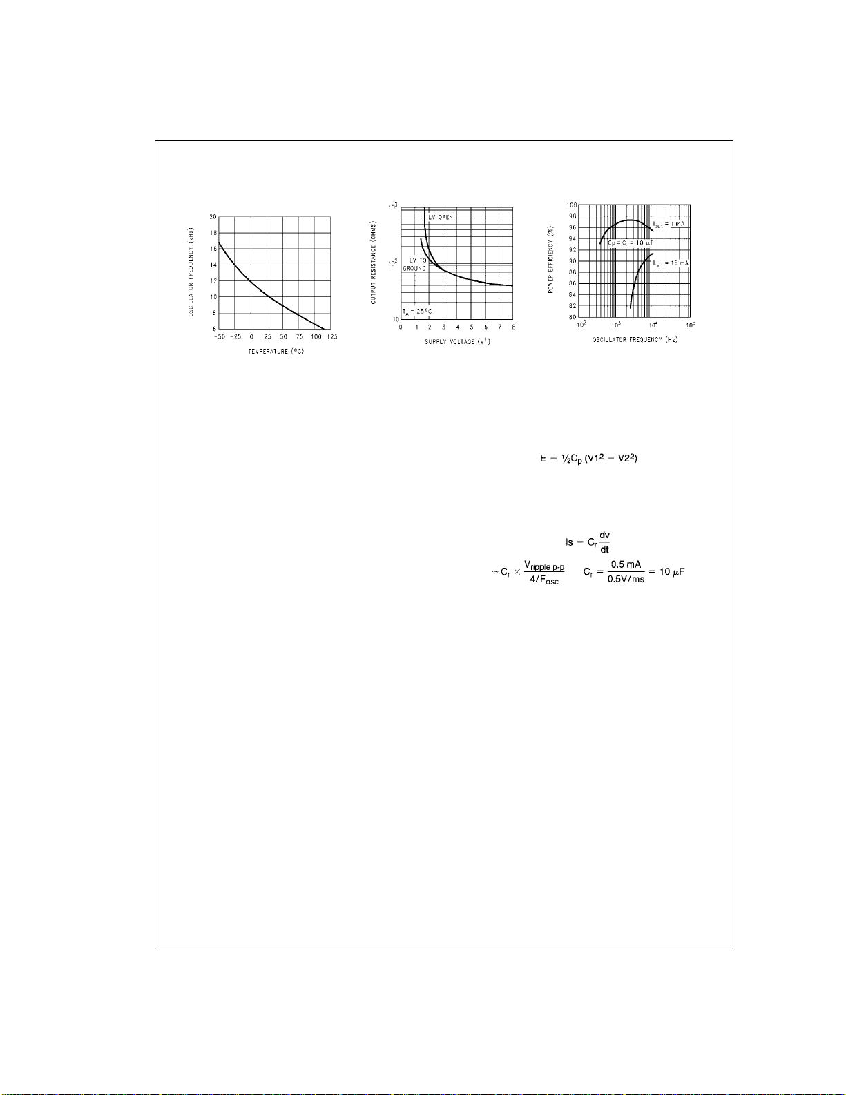
P
eff
vs OSC Freq.
@
V
+
=
5V
DS009136-26
www.national.com 4
器件 Datasheet 文档搜索
AiEMA 数据库涵盖高达 72,405,303 个元件的数据手册,每天更新 5,000 多个 PDF 文件
