Datasheet 搜索 > 运算放大器 > Microchip(微芯) > MCP609T-I/ST 数据手册 > MCP609T-I/ST 其他数据使用手册 4/32 页
 器件3D模型
¥ 3.599
MCP609T-I/ST 其他数据使用手册 - Microchip(微芯)
制造商:
Microchip(微芯)
分类:
运算放大器
封装:
TSSOP-14
Pictures:
3D模型
符号图
焊盘图
引脚图
产品图
页面导航:
导航目录
MCP609T-I/ST数据手册
Page:
of 32 Go
若手册格式错乱,请下载阅览PDF原文件
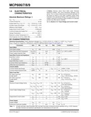
MCP606/7/8/9
DS11177E-page 4 © 2008 Microchip Technology Inc.
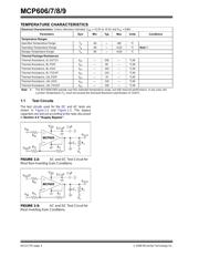
TEMPERATURE CHARACTERISTICS
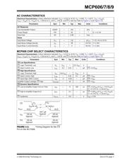
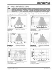
1.1 Test Circuits
The test circuits used for the DC and AC tests are
shown in Figure 1-2 and Figure 1-3. The bypass
capacitors are laid out according to the rules discussed
in Section 4.5 “Supply Bypass”.
FIGURE 1-2: AC and DC Test Circuit for
Most Non-Inverting Gain Conditions.
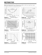
FIGURE 1-3: AC and DC Test Circuit for
Most Inverting Gain Conditions.
Electrical Characteristics: Unless otherwise indicated, V
DD
= +2.5V to +5.5V and V
SS
= GND.
Parameters Sym Min Typ Max Units Conditions
Temperature Ranges
Specified Temperature Range T
A
-40 — +85 °C
Operating Temperature Range T
A
-40 — +125 °C Note 1
Storage Temperature Range T
A
-65 — +150 °C
Thermal Package Resistances
Thermal Resistance, 5L-SOT23 θ
JA
— 256 — °C/W
Thermal Resistance, 8L-PDIP θ
JA
—85—°C/W
Thermal Resistance, 8L-SOIC θ
JA
— 163 — °C/W
Thermal Resistance, 8L-TSSOP θ
JA
— 124 — °C/W
Thermal Resistance, 14L-PDIP θ
JA
—70—°C/W
Thermal Resistance, 14L-SOIC θ
JA
— 120 — °C/W
Thermal Resistance, 14L-TSSOP θ
JA
— 100 — °C/W
Note 1: The MCP606/7/8/9 operate over this extended temperature range, but with reduced performance. In any case, the
Junction Temperature (T
J
) must not exceed the Absolute Maximum specification of +150°C.
V
DD
MCP60X
R
G
R
F
R
N
V
OUT
V
IN
V
DD
/2
1µF
C
L
R
L
V
L
0.1 µF
V
DD
MCP60X
R
G
R
F
R
N
V
OUT
V
DD
/2
V
IN
1µF
C
L
R
L
V
L
0.1 µF
器件 Datasheet 文档搜索
AiEMA 数据库涵盖高达 72,405,303 个元件的数据手册,每天更新 5,000 多个 PDF 文件
