Datasheet 搜索 > 微控制器 > TI(德州仪器) > MSP430F2617TZQW 数据手册 > MSP430F2617TZQW 其他数据使用手册 4/21 页
 器件3D模型
¥ 55.353
MSP430F2617TZQW 其他数据使用手册 - TI(德州仪器)
制造商:
TI(德州仪器)
分类:
微控制器
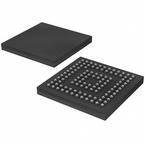
封装:
BGA-113
描述:
混合信号微控制器 MIXED SIGNAL MICROCONTROLLER
Pictures:
3D模型
符号图
焊盘图
引脚图
产品图
页面导航:
标记信息在P3
应用领域在P21
导航目录
MSP430F2617TZQW数据手册
Page:
of 21 Go
若手册格式错乱,请下载阅览PDF原文件

Detailed Bug Description
www.ti.com
3 Detailed Bug Description
ADC18 ADC12 Module
Function Incorrect conversion result in extended sample mode
Description The ADC12 conversion result can be incorrect if the extended sample mode is selected
(SHP = 0), the conversion clock is not the internal ADC12 oscillator (ADC12SSEL > 0),
and one of the following two conditions is true:
- The extended sample input signal SHI is asynchronous to the clock source used for
ADC12CLK and the undivided ADC12 input clock frequency exceeds 3.15 MHz.
or
- The extended sample input signal SHI is synchronous to the clock source used for
ADC12CLK and the undivided ADC12 input clock frequency exceeds 6.3 MHz.
Workaround - Use the pulse sample mode (SHP = 1).
or
- Use the ADC12 internal oscillator as the ADC12 clock source.
or
- Limit the undivided ADC12 input clock frequency to 3.15 MHz.
or
- Use the same clock source (such as ACLK or SMCLK) to derive both SHI and
ADC12CLK, to achieve synchronous operation, and also limit the undivided ADC12 input
clock frequency to 6.3 MHz.
ADC19 ADC12 Module
Function Sample start in extended pulse mode
Description When operating in extended pulse mode, if ADC12SC is set in the same instruction as
the first setting of ENC, a sample is not started (that is, the ADC12SC bit has no effect).
Instead, ENC must be set at least one instruction prior to the first occurrence of
ADC12SC being set.
Workaround Set ENC in a separate instruction prior to setting ADC12SC.
ADC25 ADC12 Module
Function Write to ADC12CTL0 triggers ADC12 when CONSEQ = 00
Description If ADC conversions are triggered by the Timer_B module and the ADC12 is in single-
channel single-conversion mode (CONSEQ = 00), ADC sampling is enabled by write
access to any bit(s) in the ADC12CTL0 register. This is contrary to the expected
behavior that only the ADC12 enable conversion bit (ADC12ENC) triggers a new ADC12
sample.
Workaround When operating the ADC12 in CONSEQ=00 and a Timer_B output is selected as the
sample and hold source, temporarily clear the ADC12ENC bit before writing to other bits
in the ADC12CTL0 register. The following capture trigger can then be re-enabled by
setting ADC12ENC = 1.
4
MSP430F2617 Device Erratasheet SLAZ187I–October 2012–Revised April 2015
Submit Documentation Feedback
Copyright © 2012–2015, Texas Instruments Incorporated
器件 Datasheet 文档搜索
AiEMA 数据库涵盖高达 72,405,303 个元件的数据手册,每天更新 5,000 多个 PDF 文件
