Datasheet 搜索 > 微控制器 > TI(德州仪器) > MSP430F2617TZQW 数据手册 > MSP430F2617TZQW 其他数据使用手册 5/21 页
 器件3D模型
¥ 55.404
MSP430F2617TZQW 其他数据使用手册 - TI(德州仪器)
制造商:
TI(德州仪器)
分类:
微控制器
封装:
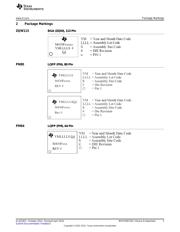
BGA-113
描述:
混合信号微控制器 MIXED SIGNAL MICROCONTROLLER
Pictures:
3D模型
符号图
焊盘图
引脚图
产品图
页面导航:
标记信息在P3
应用领域在P21
导航目录
MSP430F2617TZQW数据手册
Page:
of 21 Go
若手册格式错乱,请下载阅览PDF原文件
www.ti.com
Detailed Bug Description
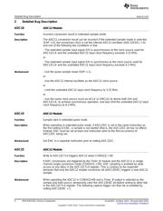
BCL12 BCS Module
Function Switching RSELx or modifying DCOCTL can cause DCO dead time or a complete DCO
stop
Description After switching RSELx bits (located in register BCSCTL1) from a value of >13 to a value
of <12 OR from a value of <12 to a value of >13, the resulting clock delivered by the
DCO can stop before the new clock frequency is applied. This dead time is
approximately 20 us. In some instances, the DCO may completely stop, requiring a
power cycle.
Furthermore, if all of the RSELx bits in the BSCTL1 register are set, modifying the
DCOCTL register to change the DCOx or the MODx bits could also result in DCO dead
time or DCO hang up.
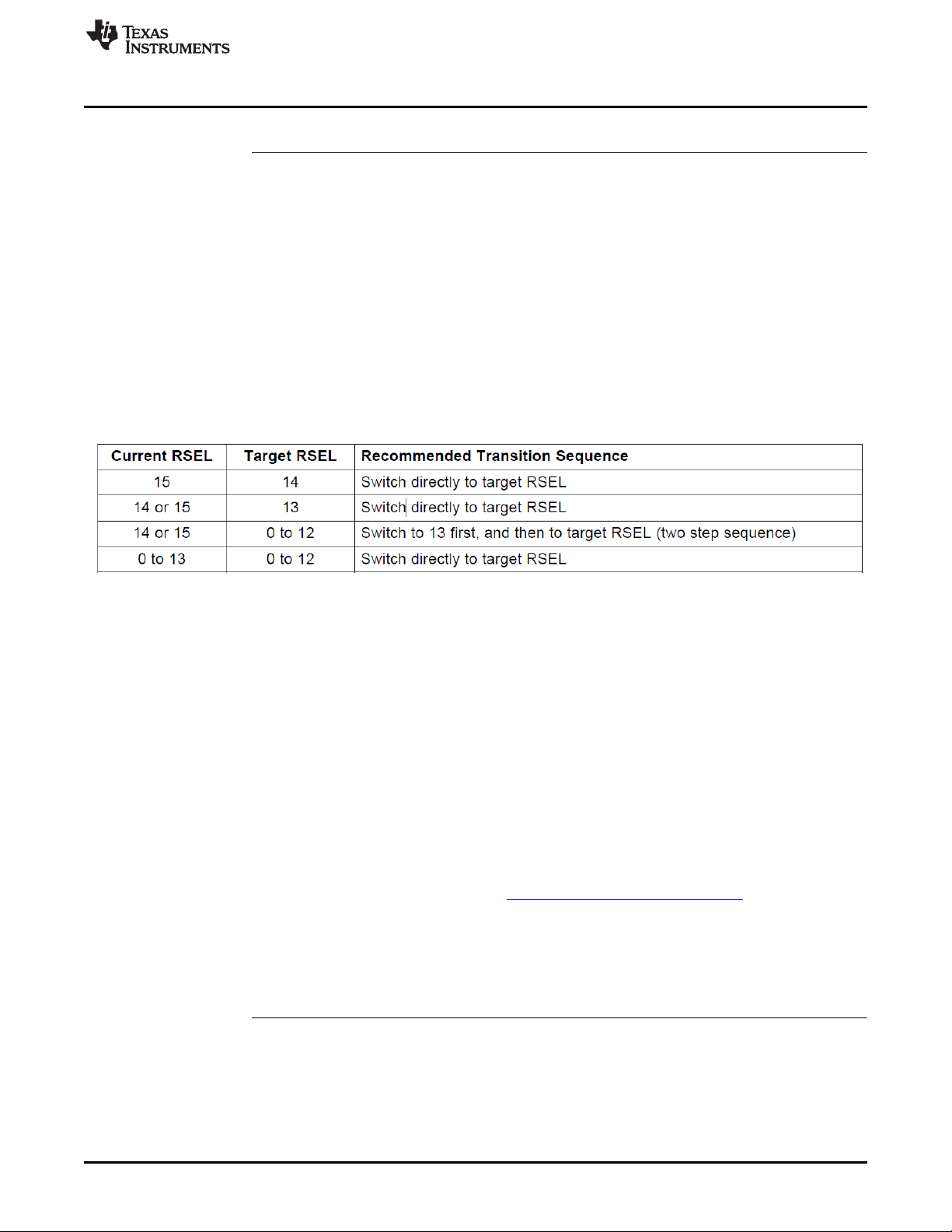
Workaround - When switching RSEL from >13 to <12, use an intermediate frequency step. The
intermediate RSEL value should be 13.
AND
- When switching RSEL from <12 to >13 it's recommended to set RSEL to its default
value first (RSEL = 7) before switching to the desired target frequency.
AND
- In case RSEL is at 15 (highest setting) it's recommended to set RSEL to its default
value first (RSEL = 7) before accessing DCOCTL to modify the DCOx and MODx bits.
After the DCOCTL register modification the RSEL bits can be manipulated in an
additional step.
In the majority of cases switching directly to intermediate RSEL steps as described
above will prevent the occurrence of BCL12. However, a more reliable method can be
implemented by changing the RSEL bits step by step in order to guarantee safe function
without any dead time of the DCO.
Note that the 3-step clock startup sequence consisting of clearing DCOCTL, loading the
BCSCTL1 target value, and finally loading the DCOCTL target value as suggested in the
in the "TLV Structure" chapter of the MSP430x2xx Family User's Guide is not affected by
BCL12 if (and only if) it is executed after a device reset (PUC) prior to any other
modifications being made to BCSCTL1 since in this case RSEL still is at its default value
of 7. However any further changes to the DCOx and MODx bits will require the
consideration of the workaround outlined above.
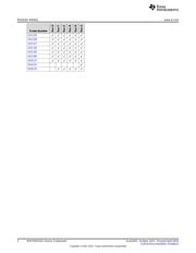
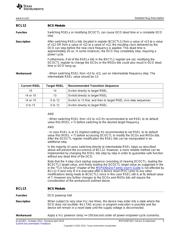
BCL13 BCS Module
Function DCO powerup halt
Description When subject to very slow Vcc rise times, the device may enter into a state where the
DCO does not oscillate. No JTAG access or program execution is possible and the
device will remain in a reset state until the supply voltage is disconnected.
Workaround Apply a Vcc poweron ramp >= 10V/second under all power-on/power-cycle scenarios.
5
SLAZ187I–October 2012–Revised April 2015 MSP430F2617 Device Erratasheet
Submit Documentation Feedback
Copyright © 2012–2015, Texas Instruments Incorporated
器件 Datasheet 文档搜索
AiEMA 数据库涵盖高达 72,405,303 个元件的数据手册,每天更新 5,000 多个 PDF 文件
