Datasheet 搜索 > AC-DC转换器 > ON Semiconductor(安森美) > NCP1055P44G 数据手册 > NCP1055P44G 其他数据使用手册 1/27 页
 器件3D模型
¥ 4.328
NCP1055P44G 其他数据使用手册 - ON Semiconductor(安森美)
制造商:
ON Semiconductor(安森美)
分类:
AC-DC转换器
封装:
DIP-8
描述:
不需要辅助偏置绕组/欠压锁定/热关闭
Pictures:
3D模型
符号图
焊盘图
引脚图
产品图
页面导航:
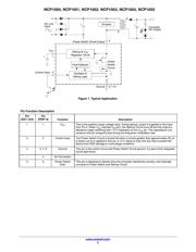
典型应用电路图在P1P2
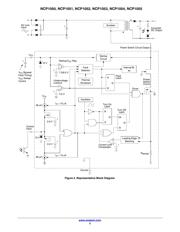
原理图在P3
封装尺寸在P24P26
型号编码规则在P1P22P23P27
标记信息在P1P25P26P27
封装信息在P22P23
功能描述在P2
应用领域在P1P16
电气规格在P7P8P9
型号编号列表在P6

导航目录
NCP1055P44G数据手册
Page:
of 27 Go
若手册格式错乱,请下载阅览PDF原文件
© Semiconductor Components Industries, LLC, 2015
April, 2015 − Rev. 14
1 Publication Order Number:
NCP1050/D
NCP1050, NCP1051,
NCP1052, NCP1053,
NCP1054, NCP1055
Monolithic High Voltage
Gated Oscillator Power
Switching Regulator
The NCP1050 through NCP1055 are monolithic high voltage
regulators that enable end product equipment to be compliant with low
standby power requirements. This device series combines the required
converter functions allowing a simple and economical power system
solution for office automation, consumer, and industrial products.
These devices are designed to operate directly from a rectified AC line
source. In flyback converter applications they are capable of providing
an output power that ranges from 6.0 W to 40 W with a fixed AC input
of 100 V, 115 V, or 230 V, and 3.0 W to 20 W with a variable AC input
that ranges from 85 V to 265 V.
This device series features an active startup regulator circuit that
eliminates the need for an auxiliary bias winding on the converter
transformer, fault detector and a programmable timer for converter
overload protection, unique gated oscillator configuration for extremely
fast loop response with double pulse suppression, power switch current
limiting, input undervoltage lockout with hysteresis, thermal shutdown,
and auto restart fault detection. These devices are available in
economical 8−pin dual−in−line and 4−pin SOT−223 packages.
Features
• Startup Circuit Eliminates the Need for Transformer Auxiliary Bias
Winding
• Optional Auxiliary Bias Winding Override for Lowest Standby
Power Applications
• Converter Output Overload and Open Loop Protection
• Auto Restart Fault Protection
• IC Thermal Fault Protection
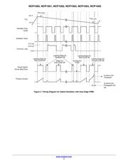
• Unique, Dual Edge, Gated Oscillator Configuration for Extremely
Fast Loop Response
• Oscillator Frequency Dithering with Controlled Slew Rate Driver for
Reduced EMI
• Low Power Consumption Allowing European Blue Angel Compliance
• On−Chip 700 V Power Switch Circuit and Active Startup Circuit
• Rectified AC Line Source Operation from 85 V to 265 V
• Input Undervoltage Lockout with Hysteresis
• Oscillator Frequency Options of 44 kHz, 100 kHz, 136 kHz
• These are Pb−Free and Halide−Free Devices
Typical Applications
• AC−DC Converters
• Wall Adapters
• Portable Electronic Chargers
• Low Power Standby and Keep−Alive Supplies
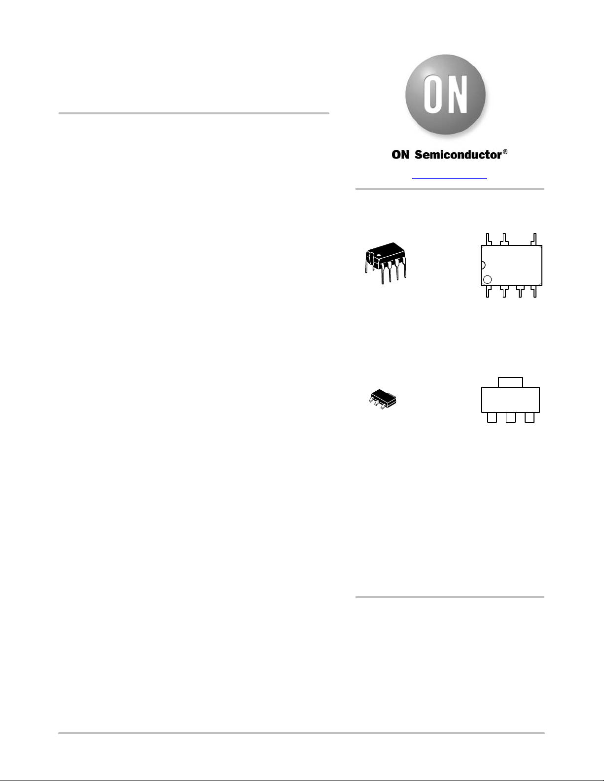
PDIP−8
P SUFFIX
CASE 626A
1
8
MARKING
DIAGRAMS
X = Current Limit (0, 1, 2, 3, 4, 5)
Z = Oscillator Frequency
A = 44 kHz, B = 100 kHz, C = 136 kHz
A = Assembly Location
WL, = Wafer Lot
YY, Y = Year
WW, W = Work Week
G or G =Pb−Free Package
1
8
Pin: 1. V
CC
2. Control Input
3, 7−8. Ground
4. No Connection
5. Power Switch Drain
NCP105XZ
AWL
YYWWG
See detailed ordering and shipping information on page 22 of
this data sheet.
ORDERING INFORMATION
www.
onsemi.com
SOT−223
ST SUFFIX
CASE 318E
Pin: 1.V
CC
2.Control Input
3.Power Switch Drain
4.Ground
1
AYW
N5XZG
G
(Note: Microdot may be in either location)
器件 Datasheet 文档搜索
AiEMA 数据库涵盖高达 72,405,303 个元件的数据手册,每天更新 5,000 多个 PDF 文件
