Datasheet 搜索 > RAM芯片 > Microchip(微芯) > PIC16F18854-I/SP 数据手册 > PIC16F18854-I/SP 其他数据使用手册 4/17 页
 器件3D模型
¥ 12.659
PIC16F18854-I/SP 其他数据使用手册 - Microchip(微芯)
制造商:
Microchip(微芯)
分类:
RAM芯片
封装:
DIP-28
描述:
PIC 32MHz 闪存:4K@x14bit RAM:512Byte
Pictures:
3D模型
符号图
焊盘图
引脚图
产品图
页面导航:
原理图在P12
技术参数、封装参数在P14
电气规格在P14
导航目录
PIC16F18854-I/SP数据手册
Page:
of 17 Go
若手册格式错乱,请下载阅览PDF原文件

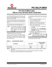
PIC16(L)F18854
DS80000698B-page 4 2016 Microchip Technology Inc.
Data Sheet Clarifications
The following typographic corrections and clarifications
are to be noted for the latest version of the device data
sheet (DS40001826A):
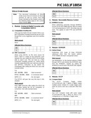
1. Module: Analog-to-Digital Converter with
Computation (ADC
2
)
In Register 23-3: ADCON2, bit 7: ADPSIS has
incorrect descriptions for its bit selections. The
correct description is below:
Note: Corrections are shown in bold. Where
possible, the original bold text formatting
has been removed for clarity.
REGISTER 23-3: ADCON2: ADC CONTROL REGISTER 2
R/W-0/0 R/W-0/0 R/W-0/0 R/W-0/0 R/W/HC-0 R/W-0/0 R/W-0/0 R/W-0/0
ADPSIS ADCRS<2:0>
(2)
ADACLR ADMD<2:0>
(1)
bit 7 bit 0
Legend:
R = Readable bit W = Writable bit U = Unimplemented bit, read as ‘0’
u = Bit is unchanged x = Bit is unknown -n/n = Value at POR and BOR/Value at all other Resets
‘1’ = Bit is set ‘0’ = Bit is cleared
bit 7 ADPSIS: ADC Previous Sample Input Select bits
1 = ADFLTR is transfered to ADPREV at start-of-conversion
0 = ADRES is transfered to ADPREV at start-of-conversion
bit 6-4 ADCRS<2:0>: ADC Accumulated Calculation Right Shift Select bits
111 = Reserved
110 = Reserved
101 through 000:
If ADMD =
100:
Low-pass filter time constant is 2
ADCRS
, filter gain is 1:1
If ADMD =
001, 010 or 011:
The accumulated value is right-shifted by ADCRS (divided by 2
ADCRS
)
(2)
Otherwise:
Bits are ignored
bit 3 ADACLR: ADC Accumulator Clear Command bit
1 = Initial clear of ADACC, ADAOV, and the sample counter. Bit is cleared by hardware.
0 = Clearing action is complete (or not started)
bit 2-0
ADMD<2:0>: ADC Operating Mode Selection bits
(1)
111 = Reserved
•
•
•
101 = Reserved
100 = Low-pass Filter mode
011 = Burst Average mode
010 = Average mode
001 = Accumulate mode
000 = Basic (Legacy) mode
Note 1: See Table 23-3 for Full-mode descriptions.
2: All results of divisions using the ADCRS bits are truncated, not rounded.
器件 Datasheet 文档搜索
AiEMA 数据库涵盖高达 72,405,303 个元件的数据手册,每天更新 5,000 多个 PDF 文件
