Datasheet 搜索 > 微控制器 > Microchip(微芯) > PIC18F67K22-I/MR 数据手册 > PIC18F67K22-I/MR 其他数据使用手册 2/17 页
 器件3D模型
¥ 39.361
PIC18F67K22-I/MR 其他数据使用手册 - Microchip(微芯)
制造商:
Microchip(微芯)
分类:
微控制器
封装:
QFN-64
描述:
MICROCHIP PIC18F67K22-I/MR 微控制器, 8位, 闪存, PIC18FxxKxx, 64 MHz, 128 KB, 4 KB, 64 引脚, QFN
Pictures:
3D模型
符号图
焊盘图
引脚图
产品图
页面导航:
封装信息在P14
电气规格在P11P12
导航目录
PIC18F67K22-I/MR数据手册
Page:
of 17 Go
若手册格式错乱,请下载阅览PDF原文件
PIC18F87K22 FAMILY
DS80000507L-page 2 2010-2015 Microchip Technology Inc.
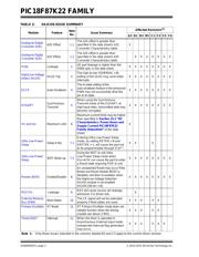
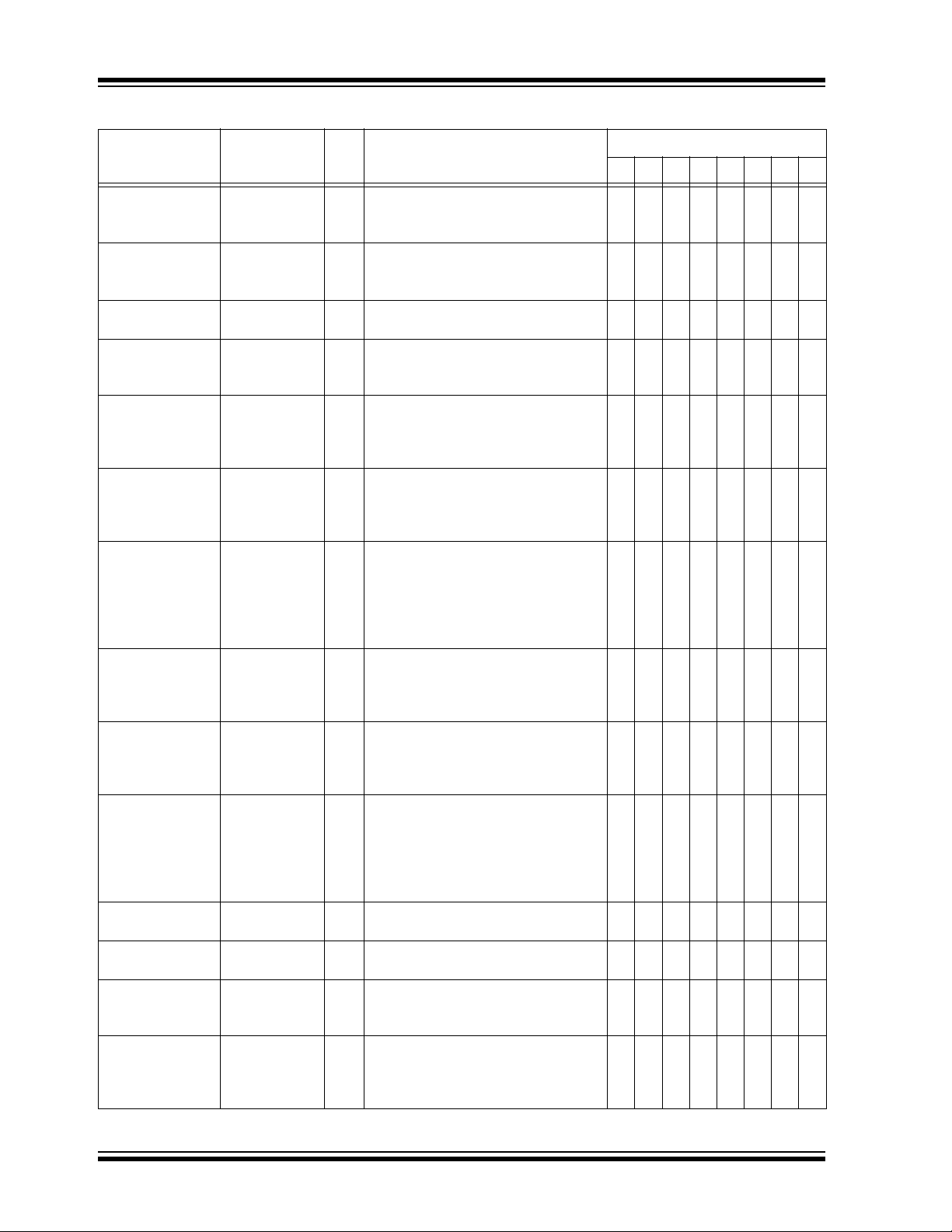
TABLE 2: SILICON ISSUE SUMMARY
Module Feature
Item
No.
Issue Summary
Affected Revisions
(1)
A3 B1 B3 B5 C1 C3 C5 C6
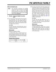
Analog-to-Digital
Converter (A/D)
A/D Offset 1.1
The A/D offset is greater than
specified in the data sheet’s A/D
Converter Characteristics table.
X
Analog-to-Digital
Converter (A/D)
A/D Offset 1.2
The A/D offset is greater than
specified in the data sheet’s A/D
Converter Characteristics table.
XXXXXXX
Ports Leakage 2.
I/O port leakage is higher than the
D060 spec in the data sheet.
XXXXXXXX
High/Low-Voltage
Detect (HLVD)
HLVD Trip 3.
The high-to-low (VDIRMAG = 0)
setting of the HLVD may send initial
interrupts.
XXXXXXXX
ECCP Auto-Shutdown 4.
The tri-state setting of the
auto-shutdown feature in the enhanced
PWM may not successfully drive the
pin to tri-state.
XXXXXXXX
EUSART
Synchronous
Transmit
5.
When using the Synchronous
Transmit mode of the EUSART, at
high baud rates, transmitted data may
become corrupted.
XXXXXXXX
I
PD and IDD Maximum Limit 6.
Maximum current limits may be higher
than specified in Section 31.2 “DC
Characteristics: Power-Down and
Supply Current PIC18F87K22
Family (Industrial)” of the data
sheet.
X
Ultra Low-Power
Sleep
Sleep Entry 7.1
Entering Ultra Low-Power Sleep
mode, by setting RETEN = 0 and
SRETEN = 1, will cause the part not
to be programmable through ICSP™.
XX X
Ultra Low-Power
Sleep
WDT Wake-up 7.2
Using the WDT to exit Ultra
Low-Power Sleep mode when
V
DD>4.5V can cause the part to enter
a Reset state requiring POR to exit.
XXXXXXXX
Resets (BOR) Enable/Disable 8.
An unexpected Reset may occur if the
Brown-out Reset module (BOR) is
disabled, and then re-enabled, when
the High/Low-Voltage Detection
(HLVD) module is not enabled
(HLVDCON<4> = 0).
XXXXXXXX
RG5 Pin Leakage 9.
RG5 will cause excess pin leakage
whenever it is driven low.
X
External Memory
Bus (EMB)
Wait States 10.
The CE signal will not be extended
properly if Wait states are used.
XXX XX
Primary Oscillator XT Mode 11. XT Primary Oscillator mode does not
reliably function when the driving
crystals are above 3 MHz.
XXX XX
Timer1/3/5/7 Interrupt 12. When the timer is operated in
Asynchronous External Input mode,
unexpected interrupt flag generation
may occur.
XXX XXX
Note 1: Only those issues indicated in the columns labeled B3 and C3 apply to the current silicon revision.
器件 Datasheet 文档搜索
AiEMA 数据库涵盖高达 72,405,303 个元件的数据手册,每天更新 5,000 多个 PDF 文件
