Datasheet 搜索 > 开发套件 > TI(德州仪器) > DRV8842EVM 数据手册 > DRV8842EVM 产品设计参考手册 6/14 页

¥ 178.8
DRV8842EVM 产品设计参考手册 - TI(德州仪器)
制造商:
TI(德州仪器)
分类:
开发套件
描述:
TEXAS INSTRUMENTS DRV8842EVM 评估模块, DRV8842EVM
Pictures:
3D模型
符号图
焊盘图
引脚图
产品图
页面导航:
典型应用电路图在P6
原理图在P4P6P13
应用领域在P13

导航目录
DRV8842EVM数据手册
Page:
of 14 Go
若手册格式错乱,请下载阅览PDF原文件
DK-LM3S-DRV8312 BASEBOARD
HARDWARE REFERENCE GUIDE
Rev. 1.0
Board Power
The board is separated into two power domains*: (1)the low voltage Controller Power
domain powers the controller and the logic circuit present on the board, and (2) the medium
voltage power delivery line that is used to carry the medium voltage and current such as the
DC power for the Inverter (also referred to as DC Bus).
1)
Controller Power comprised of the 12 V, 5 V, and 3.3 V that the board uses to power the
controller and the logic and sensing circuit present on the board. This power can be sourced
from two places (Jumper JP1 selects between the two):
• +12V
DC control power entry: Connect an external bench supply with 1A current limit
here
• On board regulator, VR1: +12V is regulated from DC bus power via an on-board buck
regulator
2) DC Bus Power is the medium voltage line – up to 52.5V - that provides the voltage to the
inverter stage to generate three phases to control the motor(s). Connect supplied 24 V
regulator to J9.
For step-by-step instructions on configuring the DRV8312 baseboard for use with a Stellaris
controlCARD, see the DK-LM3S-DRV8312 Read Me First document.
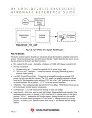
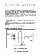
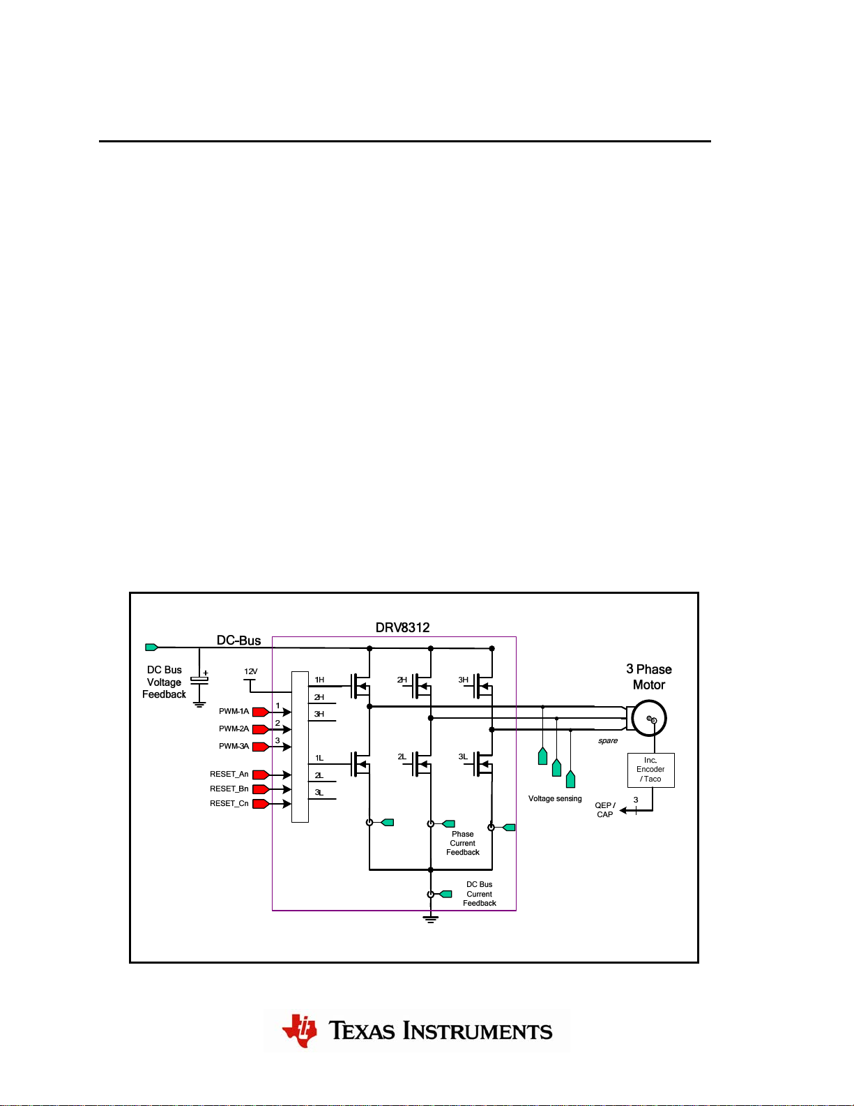
DRV8312 Functional Block Diagram
Figure 5. DRV8312 Functional Diagram
6
器件 Datasheet 文档搜索
AiEMA 数据库涵盖高达 72,405,303 个元件的数据手册,每天更新 5,000 多个 PDF 文件
