Datasheet 搜索 > 接口芯片 > NXP(恩智浦) > PCA9500PW,112 数据手册 > PCA9500PW,112 产品设计参考手册 6/64 页
 器件3D模型
¥ 0.8
PCA9500PW,112 产品设计参考手册 - NXP(恩智浦)
制造商:
NXP(恩智浦)
分类:
接口芯片
封装:
TSSOP-16
描述:
NXP PCA9500PW,112 芯片, 输入/输出扩展器, I2C, 8位, 16TSSOP
Pictures:
3D模型
符号图
焊盘图
引脚图
产品图
页面导航:
应用领域在P62
电气规格在P46


导航目录
PCA9500PW,112数据手册
Page:
of 64 Go
若手册格式错乱,请下载阅览PDF原文件
UM10204 All information provided in this document is subject to legal disclaimers. © NXP Semiconductors N.V. 2014. All rights reserved.
User manual Rev. 6 — 4 April 2014 6 of 64
NXP Semiconductors
UM10204
I
2
C-bus specification and user manual
2.3 IC designer benefits
Designers of microcontrollers are frequently under pressure to conserve output pins. The
I
2
C protocol allows connection of a wide variety of peripherals without the need for
separate addressing or chip enable signals. Additionally, a microcontroller that includes an
I
2
C interface is more successful in the marketplace due to the wide variety of existing
peripheral devices available.
3. The I
2
C-bus protocol
3.1 Standard-mode, Fast-mode and Fast-mode Plus I
2
C-bus protocols
Two wires, serial data (SDA) and serial clock (SCL), carry information between the
devices connected to the bus. Each device is recognized by a unique address (whether
it is a microcontroller, LCD driver, memory or keyboard interface) and can operate as
either a transmitter or receiver, depending on the function of the device. An LCD driver
may be only a receiver, whereas a memory can both receive and transmit data. In addition
to transmitters and receivers, devices can also be considered as masters or slaves when
performing data transfers (see Table 1
). A master is the device which initiates a data
transfer on the bus and generates the clock signals to permit that transfer. At that time,
any device addressed is considered a slave.
The I
2
C-bus is a multi-master bus. This means that more than one device capable of
controlling the bus can be connected to it. As masters are usually microcontrollers, let us
consider the case of a data transfer between two microcontrollers connected to the
I
2
C-bus (see Figure 2).
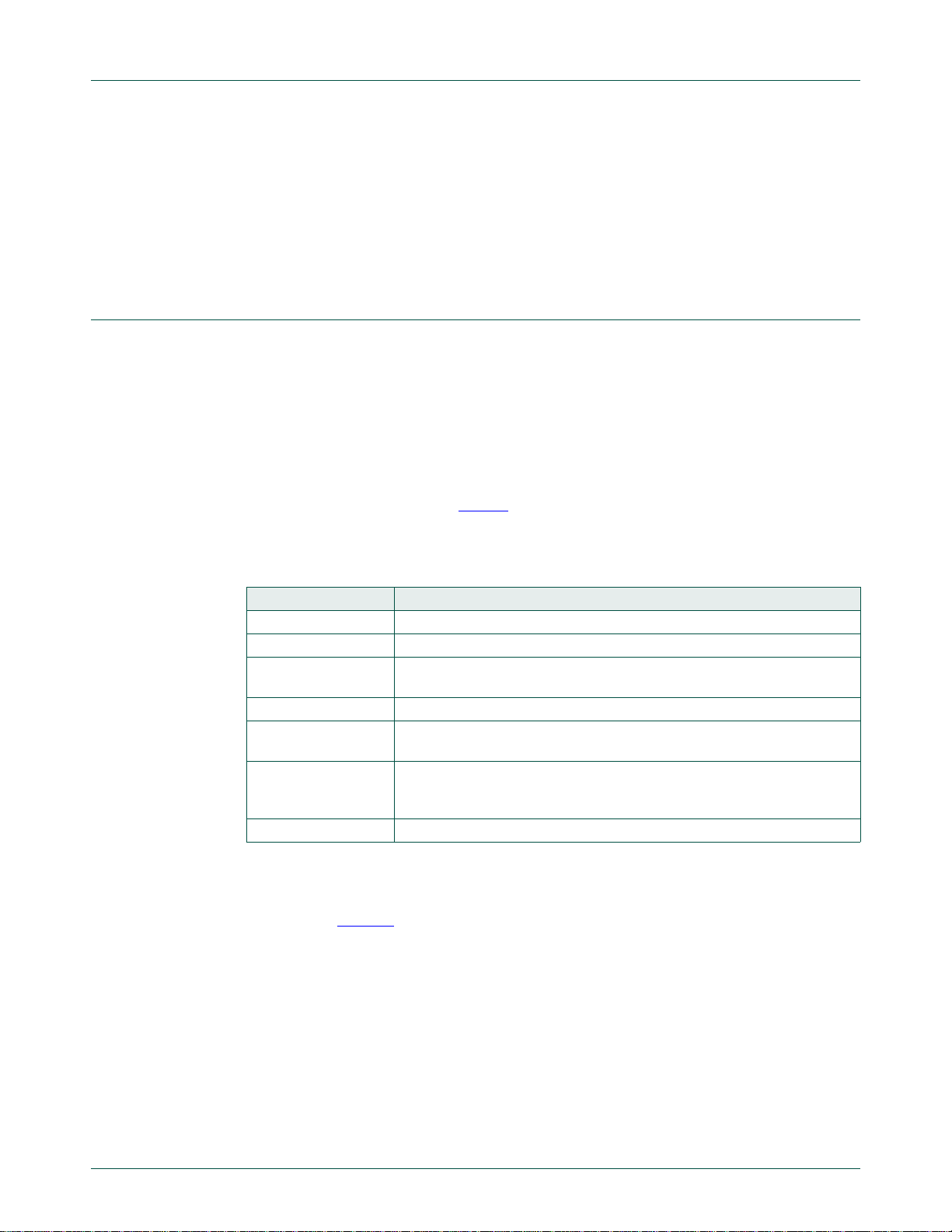
Table 1. Definition of I
2
C-bus terminology
Term Description
Transmitter the device which sends data to the bus
Receiver the device which receives data from the bus
Master the device which initiates a transfer, generates clock signals and
terminates a transfer
Slave the device addressed by a master
Multi-master more than one master can attempt to control the bus at the same time
without corrupting the message
Arbitration procedure to ensure that, if more than one master simultaneously tries to
control the bus, only one is allowed to do so and the winning message is
not corrupted
Synchronization procedure to synchronize the clock signals of two or more devices
器件 Datasheet 文档搜索
AiEMA 数据库涵盖高达 72,405,303 个元件的数据手册,每天更新 5,000 多个 PDF 文件
