Datasheet 搜索 > 开发套件 > TI(德州仪器) > TMP112EVM 数据手册 > TMP112EVM 产品设计参考手册 1/24 页

¥ 1074.335
TMP112EVM 产品设计参考手册 - TI(德州仪器)
制造商:
TI(德州仪器)
分类:
开发套件
描述:
TEXAS INSTRUMENTS TMP112EVM 评估电路板, 温度传感器 新
Pictures:
3D模型
符号图
焊盘图
引脚图
产品图
页面导航:
原理图在P5P6P18
应用领域在P21P24
导航目录
TMP112EVM数据手册
Page:
of 24 Go
若手册格式错乱,请下载阅览PDF原文件

User's Guide
SBOU144–August 2014
TMP112EVM Evaluation Board and Software Tutorial
This user's guide describes the characteristics, operation, and use of the TMP112EVM evaluation board.
This guide discusses how to set up and configure the software and hardware and reviews various aspects
of the program operation. Throughout this document, the terms evaluation board, evaluation module, and
EVM are synonymous with the TMP112EVM. This user's guide also includes information regarding
operating procedures and input/output connections, an electrical schematic, printed circuit board (PCB)
layout drawings, and a parts list for the EVM.
Contents
1 Overview ..................................................................................................................... 2
2 TMP112EVM Hardware Setup............................................................................................. 4
3 TMP112EVM Hardware..................................................................................................... 6
4 TMP112EVM Software...................................................................................................... 9
5 TMP112EVM Software Overview ........................................................................................ 11
6 TMP112 Documentation................................................................................................... 18
List of Figures
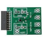
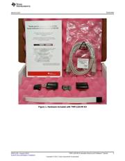
1 Hardware Included with TMP112EVM Kit ................................................................................ 3
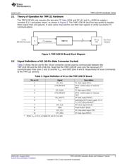
2 TMP112EVM Hardware Setup............................................................................................. 4
3 TMP112EVM Board Block Diagram....................................................................................... 5
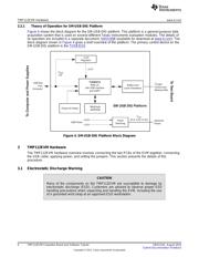
4 SM-USB-DIG Platform Block Diagram.................................................................................... 6
5 Connecting SM-USB-DIG Platform........................................................................................ 7
6 Confirmation of SM-USB-DIG Platform Driver Installation ............................................................. 7
7 10-Pin Ribbon Cable Extender............................................................................................. 8
8 TMP112EVM Software Installation........................................................................................ 9
9 TMP112EVM License Agreements ...................................................................................... 10
10 TMP112EVM Software Interface......................................................................................... 11
11 TMP112EVM Software: Communication Error with the SM-USB-DIG Platform ................................... 11
12 TMP112 Reading from Registers ........................................................................................ 12
13 TMP112 Writing to Registers ............................................................................................. 13
14 Reading the Temperature Gauge........................................................................................ 14
15 Configuring the Polarity.................................................................................................... 14
16 Active and Shutdown Mode............................................................................................... 15
17 Extended and Normal Mode.............................................................................................. 15
18 Comparator and Interrupt Mode.......................................................................................... 15
19 Conversion Rate............................................................................................................ 16
20 Setting the Fault Queue ................................................................................................... 16
21 Setting the Path for the Log File ......................................................................................... 16
22 Alert Config Box ............................................................................................................ 17
23 Register Tab ................................................................................................................ 17
24 TMP112EVM Board Schematic .......................................................................................... 18
25 TMP112EVM PCB Top Layer (Component Side)...................................................................... 19
26 TMP112EVM PCB Bottom Layer ........................................................................................ 19
1
SBOU144–August 2014 TMP112EVM Evaluation Board and Software Tutorial
Submit Documentation Feedback
Copyright © 2014, Texas Instruments Incorporated
器件 Datasheet 文档搜索
AiEMA 数据库涵盖高达 72,405,303 个元件的数据手册,每天更新 5,000 多个 PDF 文件
