Datasheet 搜索 > DSP数字信号处理器 > TI(德州仪器) > TMS320C5535AZHHA05 数据手册 > TMS320C5535AZHHA05 产品设计参考手册 6/558 页
¥ 5.98
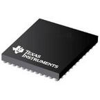
TMS320C5535AZHHA05 产品设计参考手册 - TI(德州仪器)
制造商:
TI(德州仪器)
分类:
DSP数字信号处理器
封装:
BGA-144
描述:
TMS320C5535 , C5534 , C5533 , C5532定点数字信号处理器 TMS320C5535, C5534, C5533,C5532 FIXED-POINT DIGITAL SIGNAL PROCESSORS
Pictures:
3D模型
符号图
焊盘图
引脚图
产品图
页面导航:
引脚图在P344P455Hot
典型应用电路图在P285P286
原理图在P37P38P118P138P163P190P204P205P255P256P285P310
功能描述在P52P127P137
应用领域在P558
导航目录
TMS320C5535AZHHA05数据手册
Page:
of 558 Go
若手册格式错乱,请下载阅览PDF原文件

www.ti.com
6
SPRUH87H–August 2011–Revised April 2016
Submit Documentation Feedback
Copyright © 2011–2016, Texas Instruments Incorporated
Contents
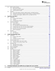
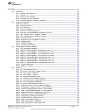
6.4.21 SDIO Interrupt Status Register (SDIOIST).................................................................. 251
6.4.22 SD FIFO Control Register (SDFIFOCTL).................................................................... 252
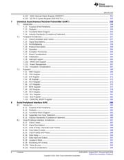
7 Universal Asynchronous Receiver/Transmitter (UART) ......................................................... 253
7.1 Introduction ................................................................................................................ 254
7.1.1 Purpose of the Peripheral....................................................................................... 254
7.1.2 Features........................................................................................................... 254
7.1.3 Functional Block Diagram ...................................................................................... 255
7.1.4 Industry Standard(s) Compliance Statement................................................................. 255
7.2 Peripheral Architecture................................................................................................... 257
7.2.1 Clock Generation and Control.................................................................................. 257
7.2.2 Signal Descriptions .............................................................................................. 259
7.2.3 Pin Multiplexing .................................................................................................. 259
7.2.4 Protocol Description............................................................................................. 259
7.2.5 Operation ......................................................................................................... 260
7.2.6 Exception Processing ........................................................................................... 264
7.2.7 Reset Considerations ........................................................................................... 264
7.2.8 Initialization ....................................................................................................... 265
7.2.9 Interrupt Support................................................................................................. 265
7.2.10 DMA Event Support ............................................................................................ 266
7.2.11 Power Management............................................................................................ 267
7.2.12 Emulation Considerations ..................................................................................... 267
7.3 Registers................................................................................................................... 268
7.3.1 RBR Register..................................................................................................... 269
7.3.2 THR Register .................................................................................................... 270
7.3.3 IER Register ..................................................................................................... 271
7.3.4 IIR Register....................................................................................................... 272
7.3.5 FCR Register..................................................................................................... 273
7.3.6 LCR Register..................................................................................................... 275
7.3.7 MCR Register .................................................................................................... 277
7.3.8 LSR Register ..................................................................................................... 278
7.3.9 SCR Register..................................................................................................... 280
7.3.10 DLL Register .................................................................................................... 281
7.3.11 DLH Register.................................................................................................... 281
7.3.12 PWREMU_MGMT Register ................................................................................... 283
8 Serial Peripheral Interface (SPI).......................................................................................... 284
8.1 Introduction ................................................................................................................ 285
8.1.1 Purpose of the Peripheral....................................................................................... 285
8.1.2 Features........................................................................................................... 285
8.1.3 Functional Block Diagram ...................................................................................... 285
8.1.4 Supported Use Case Statement............................................................................... 286
8.1.5 Industry Standard(s) Compliance Statement................................................................. 286
8.2 Serial Peripheral Interface Architecture................................................................................ 287
8.2.1 Clock Control..................................................................................................... 287
8.2.2 Signal Descriptions .............................................................................................. 288
8.2.3 Units of Data: Characters and Frames........................................................................ 288
8.2.4 Chip Select Control.............................................................................................. 288
8.2.5 Clock Polarity and Phase....................................................................................... 288
8.2.6 Data Delay........................................................................................................ 290
8.2.7 Data Input and Output........................................................................................... 291
8.2.8 Loopback Mode.................................................................................................. 291
8.2.9 Monitoring SPI Activity .......................................................................................... 291
8.2.10 Slave Access.................................................................................................... 292
8.2.11 Reset Considerations .......................................................................................... 294
器件 Datasheet 文档搜索
AiEMA 数据库涵盖高达 72,405,303 个元件的数据手册,每天更新 5,000 多个 PDF 文件

