Datasheet 搜索 > 微控制器 > NXP(恩智浦) > MC9S08JM32CGT 数据手册 > MC9S08JM32CGT 用户编程技术手册 5/18 页
 器件3D模型
¥ 7.191
MC9S08JM32CGT 用户编程技术手册 - NXP(恩智浦)
制造商:
NXP(恩智浦)
分类:
微控制器
封装:
QFN-48
描述:
NXP MC9S08JM32CGT 芯片, 微控制器, 8位, S08, 32K闪存, QFN48
Pictures:
3D模型
符号图
焊盘图
引脚图
产品图
页面导航:
应用领域在P6
导航目录
MC9S08JM32CGT数据手册
Page:
of 18 Go
若手册格式错乱,请下载阅览PDF原文件

Bootloader Overview
USB Bootloader for the MC9S08JM60, Rev. 1
Freescale Semiconductor 5
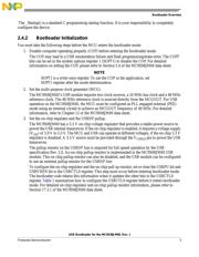
The _Startup() is a standard C programming startup function. It is your responsibility to completely
configure the device.
2.4.2 Bootloader Initialization
You must take the following steps before the MCU enters the bootloader mode:
1. Disable computer operating properly (COP) before entering the bootloader mode.
The COP may lead to a USB enumeration failure and flash programming/erase error. The COPT
bits can be set in the system options register 1 (SOPT1) to disable the COP. For detailed
information on setting the COP, please refer to Section 5.4 of the MC9S08JM60 data sheet.
NOTE
SOPT1 is a write-once register. To use the COP in the application, set
SOPT1 register after the mode determination.
2. Set the multi-purpose clock generator (MCG).
The MC9S08JM60’s USB module requires two clock sources, a 24 MHz bus clock and a 48 MHz
reference clock. The 48 MHz reference clock is sourced directly from the MCGOUT. For USB
operation on the MC9S08JM60, the MCG must be configured as PLL engaged external (PEE)
mode using an external crystal to achieve an MCGOUT frequency of 48 MHz. For detailed
information, refer to Chapter 12 of the MC9S08JM60 data sheet.
3. Set the on-chip regulator and the USBDP pullup.
The MC9S08JM60 has a 3.3 V on-chip voltage regulator that provides a stable power source to
power the USB internal transceiver. If the on-chip regulator is enabled, it requires a voltage supply
(V
DD
) of 3.9 V to 5.5 V. The MCU and USB can operate at different voltages, if the on-chip 3.3 V
regulator is disabled. A 3.3 V source must be provided through the V
USB33
pin to power the USB
transceiver.
The pullup resistor on the USBDP line is required for full-speed operation by the USB
specification Rev. 2.0. An on-chip pullup resistor is implemented in the MC9S08JM60 USB
module. This on-chip pullup resistor can also be disabled, and the USB module can be configured
to use an external pullup resistor for the USBDP line.
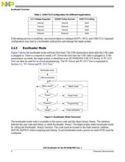
To configure the on-chip regulator and the on-chip pull up resistor, set or clear the USBPU bit and
USBVREN bit in the USBCTL0 register. This step must occur before entering bootloader mode.
The bootloader code retains this information when it updates the other bits in the USBCTL0
register. Table 1 summarizes how to configure the USBCTL0 register before it enters bootloader
mode. For detailed on-chip regulator and on-chip pullup resistor information, please refer to
Section 17.3.1 of the MC9S08JM60 data sheet.
器件 Datasheet 文档搜索
AiEMA 数据库涵盖高达 72,405,303 个元件的数据手册,每天更新 5,000 多个 PDF 文件
