Datasheet 搜索 > 微控制器 > Microchip(微芯) > PIC16C55A-20I/SP 数据手册 > PIC16C55A-20I/SP 用户编程技术手册 3/29 页
 器件3D模型
¥ 5.637
PIC16C55A-20I/SP 用户编程技术手册 - Microchip(微芯)
制造商:
Microchip(微芯)
分类:
微控制器
封装:
DIP-28
Pictures:
3D模型
符号图
焊盘图
引脚图
产品图
页面导航:
导航目录
PIC16C55A-20I/SP数据手册
Page:
of 29 Go
若手册格式错乱,请下载阅览PDF原文件
3
FN2969.5
April 4, 2005
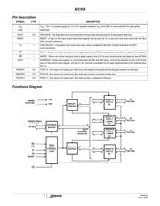
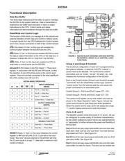
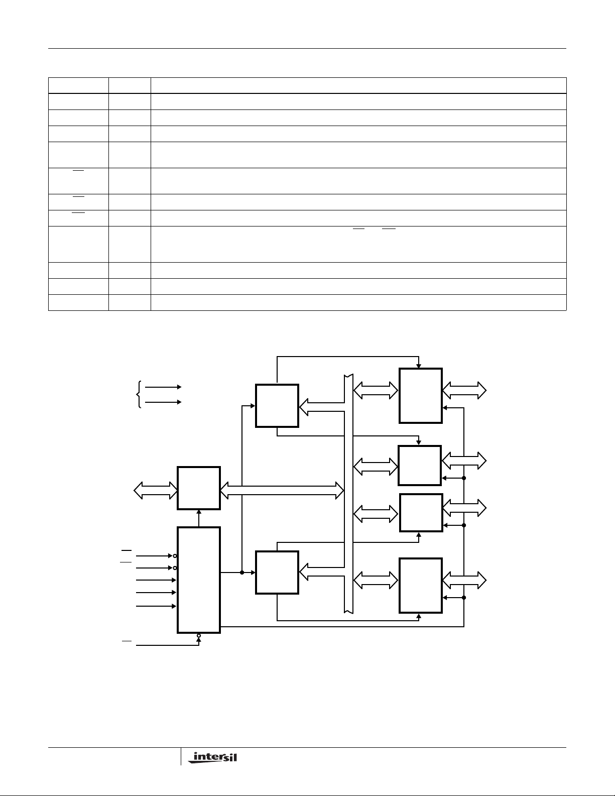
Functional Diagram
Pin Description
SYMBOL TYPE DESCRIPTION
V
CC
V
CC
: The +5V power supply pin. A 0.1µF capacitor between V
CC
and GND is recommended for decoupling.
GND GROUND
D0-D7 I/O DATA BUS: The Data Bus lines are bidirectional three-state pins connected to the system data bus.
RESET I RESET: A high on this input clears the control register and all ports (A, B, C) are set to the input mode with the “Bus
Hold” circuitry turned on.
CS
I CHIP SELECT: Chip select is an active low input used to enable the 82C55A onto the Data Bus for CPU
communications.
RD
I READ: Read is an active low input control signal used by the CPU to read status information or data via the data bus.
WR I WRITE: Write is an active low input control signal used by the CPU to load control words and data into the 82C55A.
A0-A1 I ADDRESS: These input signals, in conjunction with the RD
and WR inputs, control the selection of one of the three
ports or the control word register. A0 and A1 are normally connected to the least significant bits of the Address Bus
A0, A1.
PA0-PA7 I/O PORT A: 8-bit input and output port. Both bus hold high and bus hold low circuitry are present on this port.
PB0-PB7 I/O PORT B: 8-bit input and output port. Bus hold high circuitry is present on this port.
PC0-PC7 I/O PORT C: 8-bit input and output port. Bus hold circuitry is present on this port.
GROUP A
PORT A
(8)
GROUP A
PORT C
UPPER
(4)
GROUP B
PORT C
LOWER
(4)
GROUP B
PORT B
(8)
GROUP B
CONTROL
GROUP A
CONTROL
DATA BUS
BUFFER
READ
WRITE
CONTROL
LOGIC
RD
WR
A1
A0
RESET
CS
D7-D0
POWER
SUPPLIES
+5V
GND
BIDIRECTIONAL
DATA BUS
I/O
PA7-PA0
I/O
PC7-PC4
I/O
PC3-PC0
I/O
PB7-PB0
8-BIT
INTERNAL
DATA BUS
82C55A
器件 Datasheet 文档搜索
AiEMA 数据库涵盖高达 72,405,303 个元件的数据手册,每天更新 5,000 多个 PDF 文件
