Datasheet 搜索 > 微控制器 > Microchip(微芯) > PIC16C55A-20I/SP 数据手册 > PIC16C55A-20I/SP 用户编程技术手册 5/29 页
 器件3D模型
¥ 5.637
PIC16C55A-20I/SP 用户编程技术手册 - Microchip(微芯)
制造商:
Microchip(微芯)
分类:
微控制器
封装:
DIP-28
Pictures:
3D模型
符号图
焊盘图
引脚图
产品图
页面导航:
导航目录
PIC16C55A-20I/SP数据手册
Page:
of 29 Go
若手册格式错乱,请下载阅览PDF原文件
5
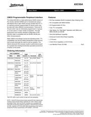
FN2969.5
April 4, 2005
two 4-bit ports under the mode control. Each 4-bit port
contains a 4-bit latch and it can be used for the control signal
output and status signal inputs in conjunction with ports A
and B. See Figure 2B.
Operational Description
Mode Selection
There are three basic modes of operation than can be
selected by the system software:
Mode 0 - Basic Input/Output
Mode 1 - Strobed Input/Output
Mode 2 - Bidirectional Bus
When the reset input goes “high”, all ports will be set to the
input mode with all 24 port lines held at a logic “one” level by
internal bus hold devices. After the reset is removed, the
82C55A can remain in the input mode with no additional
initialization required. This eliminates the need to pull-up or
pull-down resistors in all-CMOS designs. The control word
register will contain 9Bh. During the execution of the system
program, any of the other modes may be selected using a
single output instruction. This allows a single 82C55A to
service a variety of peripheral devices with a simple software
maintenance routine. Any port programmed as an output
port is initialized to all zeros when the control word is written.
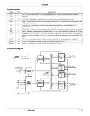
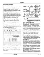
FIGURE 2A. PORT A BUS-HOLD CONFIGURATION
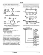
FIGURE 2B. PORT B AND C BUS-HOLD CONFIGURATION
FIGURE 2. BUS-HOLD CONFIGURATION
MASTER
RESET
OR MODE
CHANGE
INTERNAL
DATA IN
INTERNAL
DATA OUT
(LATCHED)
EXTERNAL
PORT A PIN
OUTPUT MODE
INPUT MODE
RESET
OR MODE
CHANGE
INTERNAL
DATA IN
INTERNAL
DATA OUT
(LATCHED)
EXTERNAL
PORT B, C
OUTPUT MODE
PIN
P
V
CC
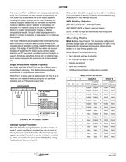
FIGURE 3. BASIC MODE DEFINITIONS AND BUS INTERFACE
DATA BUS
8I/O
B
PB7-PB0
4I/O
PC3-PC0
4I/O
C
PC7-PC4
8I/O
A
PA7-PA0
CONTROL BUS
ADDRESS BUS
RD, WR
82C55A
D7-D0 A0-A1
CS
MODE 0
8I/O
B
PB7-PB0 CONTROL
C
8I/O
A
PA7-PA0
MODE 1
OR I/O
CONTROL
OR I/O
8I/O
B
PB7-PB0
C
BI-
A
PA7-PA0
MODE 2
CONTROL
DIRECTIONAL
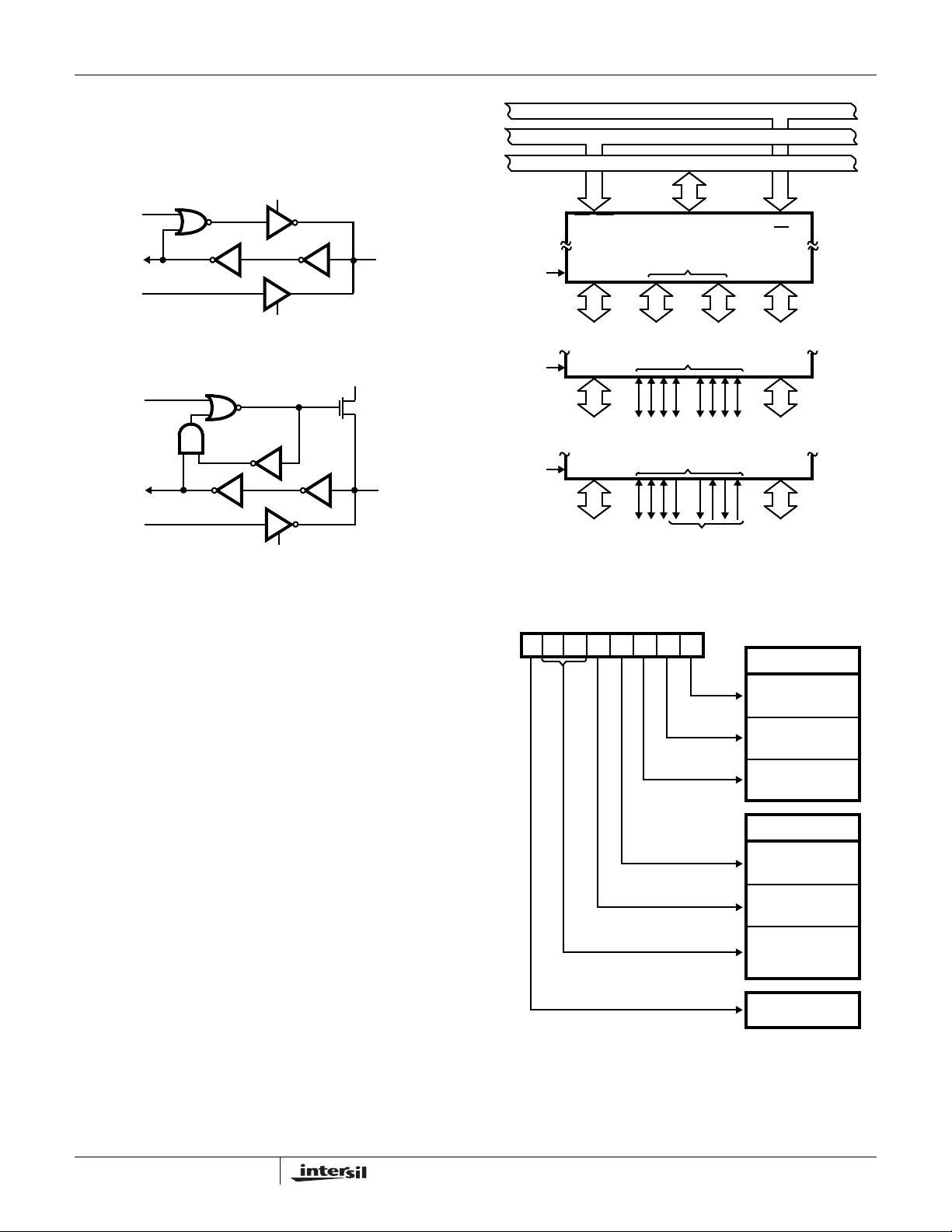
FIGURE 4. MODE DEFINITION FORMAT
D7 D6 D5 D4 D3 D2 D1 D0
PORT C (LOWER)
1 = INPUT
0 = OUTPUT
PORT B
1 = INPUT
0 = OUTPUT
MODE SELECTION
0 = MODE 0
1 = MODE 1
GROUP B
PORT C (UPPER)
1 = INPUT
0 = OUTPUT
PORT A
1 = INPUT
0 = OUTPUT
MODE SELECTION
00 = MODE 0
01 = MODE 1
GROUP A
1X = MODE 2
MODE SET FLAG
1 = ACTIVE
CONTROL WORD
82C55A
器件 Datasheet 文档搜索
AiEMA 数据库涵盖高达 72,405,303 个元件的数据手册,每天更新 5,000 多个 PDF 文件
