Datasheet 搜索 > 微控制器 > Microchip(微芯) > PIC16C55A-20I/SP 数据手册 > PIC16C55A-20I/SP 用户编程技术手册 6/29 页
 器件3D模型
¥ 5.637
PIC16C55A-20I/SP 用户编程技术手册 - Microchip(微芯)
制造商:
Microchip(微芯)
分类:
微控制器
封装:
DIP-28
Pictures:
3D模型
符号图
焊盘图
引脚图
产品图
页面导航:
导航目录
PIC16C55A-20I/SP数据手册
Page:
of 29 Go
若手册格式错乱,请下载阅览PDF原文件
6
FN2969.5
April 4, 2005
The modes for Port A and Port B can be separately defined,
while Port C is divided into two portions as required by the
Port A and Port B definitions. All of the output registers,
including the status flip-flops, will be reset whenever the
mode is changed. Modes may be combined so that their
functional definition can be “tailored” to almost any I/O
structure. For instance: Group B can be programmed in
Mode 0 to monitor simple switch closings or display
computational results, Group A could be programmed in
Mode 1 to monitor a keyboard or tape reader on an interrupt-
driven basis.
The mode definitions and possible mode combinations may
seem confusing at first, but after a cursory review of the
complete device operation a simple, logical I/O approach will
surface. The design of the 82C55A has taken into account
things such as efficient PC board layout, control signal
definition vs. PC layout and complete functional flexibility to
support almost any peripheral device with no external logic.
Such design represents the maximum use of the available
pins.
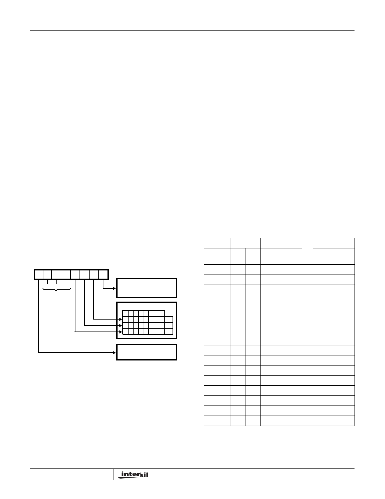
Single Bit Set/Reset Feature (Figure 5)
Any of the eight bits of Port C can be Set or Reset using a
single Output instruction. This feature reduces software
requirements in control-based applications.
When Port C is being used as status/control for Port A or B,
these bits can be set or reset by using the Bit Set/Reset
operation just as if they were output ports.
Interrupt Control Functions
When the 82C55A is programmed to operate in mode 1 or
mode 2, control signals are provided that can be used as
interrupt request inputs to the CPU. The interrupt request
signals, generated from port C, can be inhibited or enabled
by setting or resetting the associated INTE flip-flop, using
the bit set/reset function of port C.
This function allows the programmer to enable or disable a
CPU interrupt by a specific I/O device without affecting any
other device in the interrupt structure.
INTE Flip-Flop Definition
(BIT-SET)-INTE is SET - Interrupt Enable
(BIT-RESET)-INTE is Reset - Interrupt Disable
NOTE: All Mask flip-flops are automatically reset during mode
selection and device Reset.
Operating Modes
Mode 0 (Basic Input/Output). This functional configuration
provides simple input and output operations for each of the
three ports. No handshaking is required, data is simply
written to or read from a specific port.
Mode 0 Basic Functional Definitions:
• Two 8-bit ports and two 4-bit ports
• Any Port can be input or output
• Outputs are latched
• Inputs are not latched
• 16 different Input/Output configurations possible
FIGURE 5. BIT SET/RESET FORMAT
D7 D6 D5 D4 D3 D2 D1 D0
BIT SET/RESET
1 = SET
0 = RESET
BIT SELECT
0
BIT SET/RESET FLAG
CONTROL WORD
DON’T
CARE
XXX
0 = ACTIVE
1234567
01010101
00110011
00001111
B0
B1
B2
MODE 0 PORT DEFINITION
A B GROUP A
#
GROUP B
D4 D3 D1 D0 PORT A
PORT C
(Upper) PORT B
PORT C
(Lower)
0 0 0 0 Output Output 0 Output Output
0 0 0 1 Output Output 1 Output Input
0 0 1 0 Output Output 2 Input Output
0 0 1 1 Output Output 3 Input Input
0 1 0 0 Output Input 4 Output Output
0 1 0 1 Output Input 5 Output Input
0 1 1 0 Output Input 6 Input Output
0 1 1 1 Output Input 7 Input Input
1 0 0 0 Input Output 8 Output Output
1 0 0 1 Input Output 9 Output Input
1 0 1 0 Input Output 10 Input Output
1 0 1 1 Input Output 11 Input Input
1 1 0 0 Input Input 12 Output Output
1 1 0 1 Input Input 13 Output Input
1 1 1 0 Input Input 14 Input Output
1 1 1 1 Input Input 15 Input Input
82C55A
器件 Datasheet 文档搜索
AiEMA 数据库涵盖高达 72,405,303 个元件的数据手册,每天更新 5,000 多个 PDF 文件
