Datasheet 搜索 > 微控制器 > Microchip(微芯) > PIC16F716-I/P 数据手册 > PIC16F716-I/P 用户编程技术手册 5/18 页
 器件3D模型
¥ 10.39
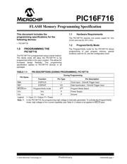
PIC16F716-I/P 用户编程技术手册 - Microchip(微芯)
制造商:
Microchip(微芯)
分类:
微控制器
封装:
PDIP-18
描述:
MICROCHIP PIC16F716-I/P 微控制器, 8位, 闪存, AEC-Q100, PIC16F, 20 MHz, 3.5 KB, 128 Byte, 18 引脚, DIP
Pictures:
3D模型
符号图
焊盘图
引脚图
产品图
页面导航:
引脚图在P1P2Hot
电气规格在P16
导航目录
PIC16F716-I/P数据手册
Page:
of 18 Go
若手册格式错乱,请下载阅览PDF原文件
2003 Microchip Technology Inc. Preliminary DS40245B-page 5
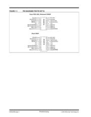
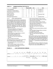
TABLE 2-1: COMMAND MAPPING FOR PIC16F716
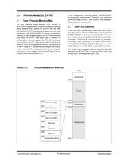
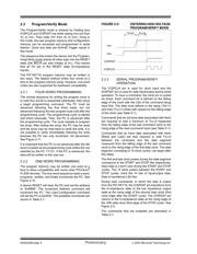
2.3.3.1 LOAD CONFIGURATION
After receiving this command and the corresponding 14
bits of configuration data, the program counter (PC) will
be set to 0x2000 and the input latch will contain the
data (see Figure 2-3). Since 0x2000 is the first user ID
location and 0x2007 is the configuration word address,
the program counter must be incremented 7 times to
access the configuration word latch. The following
sequence is recommended when reprogramming the
configuration word only:
• Send Load Configuration command with an
unprogrammed data word (i.e., 0x3FFF).
• Send Increment Program Counter command
seven times.
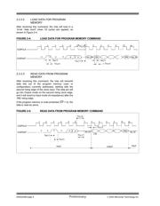
• Send Load Data For Program Memory command
with the desired configuration word.
• Send Begin Programming command
• Wait T
PROG then send End Programming
command.
• Wait T
DIS before the next action.
The following sequence may be used to program the 4
user ID locations and the configuration word:
• Send Load Configuration command with first word
of user ID data
• Send Increment Program Counter command
• Send Load Data for Program Memory command
with second word of user ID data
• Send Increment Program Counter command
• Send Load Data for Program Memory command
with third word of user ID data
• Send Increment Program Counter command
• Send Load Data for Program Memory command
with fourth word of user ID data
• Send Begin Programming command
• Wait T
PROG then send End Programming
command
• Wait T
DIS then send Increment Address command
4 times
• Send Load Data for Program Memory command-
ers configuration word data
• Send Begin Programming command
• Wait T
PROG then send End Programming
command
Unlike program memory and user ID data which must
start from the erased state before programming, the
configuration word can be reprogrammed regardless of
it's current state. The exception to this is the code pro-
tect bit (CP
) which can only be changed from '0'
(protected) to '1' (unprotected) by issuing a Bulk Erase
command.
After configuration memory is entered, the only way to
get back to the user program memory is to exit the
Program/Verify mode by taking MCLR
low (VIL).
FIGURE 2-3: LOAD CONFIGURATION COMMAND
Command Mapping (MSb … LSb) Data
Load Configuration xx00000, data (14), 0
Load Data For Program Memory xx00100, data (14), 0
Read Data From Program Memory xx01000, data (14), 0
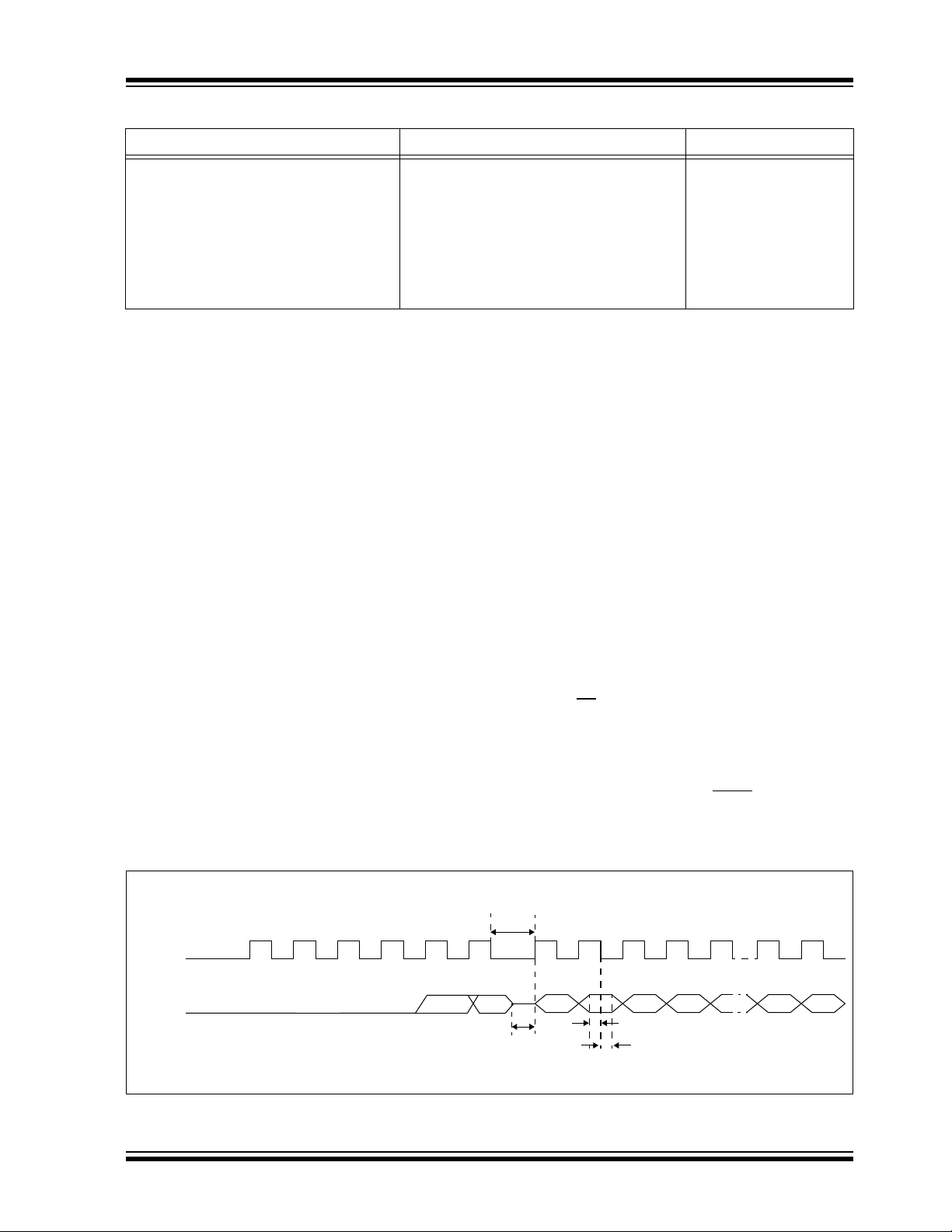
Increment Address xx0110
Begin Programming x11000Externally Timed
End Programming x01110
Bulk Erase Program Memory xx1001Internally Timed
TSET1
T
HLD1
T
DLY1
T
DLY2
12 3 4 56
000
0
X
X
12 3 4 5 15
16
strt_bit
stp_bit
LSb
MSb
0
ICSPCLK
ICSPDAT
器件 Datasheet 文档搜索
AiEMA 数据库涵盖高达 72,405,303 个元件的数据手册,每天更新 5,000 多个 PDF 文件
