Datasheet 搜索 > 32位控制器 > Microchip(微芯) > PIC32MX320F128HT-80I/MR 数据手册 > PIC32MX320F128HT-80I/MR 用户编程技术手册 1/76 页
 器件3D模型
¥ 14.643
PIC32MX320F128HT-80I/MR 用户编程技术手册 - Microchip(微芯)
制造商:
Microchip(微芯)
分类:
32位控制器
封装:
QFN-64
描述:
32位微控制器 - MCU 64Pin, 128 KB Flash 16 KB RAM, 80 MHz
Pictures:
3D模型
符号图
焊盘图
引脚图
产品图
页面导航:
引脚图在P5P6Hot
原理图在P9P72P74
电气规格在P7P8P63
导航目录
PIC32MX320F128HT-80I/MR数据手册
Page:
of 76 Go
若手册格式错乱,请下载阅览PDF原文件
2007-2016 Microchip Technology Inc. DS60001145S-page 1
PIC32
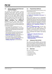
1.0 DEVICE OVERVIEW
This document defines the Flash programming
specification for the PIC32 family of 32-bit
microcontrollers.
This programming specification is designed to guide
developers of external programmer tools. Customers
who are developing applications for PIC32 devices
should use development tools that already provide
support for device programming.
The major topics of discussion include:
• Section 1.0 “Device Overview”
• Section 2.0 “Programming Overview”
• Section 3.0 “Programming Steps”
• Section 4.0 “Connecting to the Device”
• Section 5.0 “EJTAG vs. ICSP”
• Section 6.0 “Pseudo Operations”
• Section 7.0 “Entering 2-Wire Enhanced ICSP
Mode”
• Section 8.0 “Check Device Status”
• Section 9.0 “Erasing the Device”
• Section 10.0 “Entering Serial Execution Mode”
• Section 11.0 “Downloading the Programming
Executive (PE)”
• Section 12.0 “Downloading a Data Block”
• Section 13.0 “Initiating a Page Erase”
• Section 14.0 “Initiating a Flash Row Write”
• Section 15.0 “Verify Device Memory”
• Section 16.0 “Exiting Programming Mode”
• Section 17.0 “The Programming Executive”
• Section 18.0 “Checksum”
• Section 19.0 “Configuration Memory and Device
ID”
• Section 20.0 “TAP Controllers”
• Section 21.0 “AC/DC Characteristics and Timing
Requirements”
• Appendix A: “PIC32 Flash Memory Map”
• Appendix B: “Hex File Format”
• Appendix C: “Device IDs”
• Appendix D: “Revision History”
2.0 PROGRAMMING OVERVIEW
When in development of a programming tool, it is
necessary to understand the internal Flash program
operations of the target device and the Special
Function Registers (SFRs) used to control Flash
programming, as these same operations and registers
are used by an external programming tool and its
software. These operations and control registers are
described in the “Flash Program Memory” chapter in
the specific device data sheet, and the related “PIC32
Family Reference Manual” section. It is highly
recommended that these documents be used in
conjunction with this programming specification.
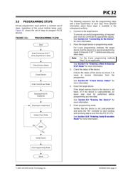
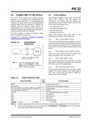
An external tool programming setup consists of an
external programmer tool and a target PIC32 device.
Figure 2-1 illustrates a typical programming setup. The
programmer tool is responsible for executing
necessary programming steps and completing the
programming operation.
FIGURE 2-1: PROGRAMMING SYSTEM
SETUP
Target PIC32 Device
CPU
On-Chip Memory
External
Programmer
PIC32 Flash Programming Specification
器件 Datasheet 文档搜索
AiEMA 数据库涵盖高达 72,405,303 个元件的数据手册,每天更新 5,000 多个 PDF 文件
