Datasheet 搜索 > 32位控制器 > Microchip(微芯) > PIC32MX320F128HT-80I/MR 数据手册 > PIC32MX320F128HT-80I/MR 用户编程技术手册 2/76 页
 器件3D模型
¥ 2.03
PIC32MX320F128HT-80I/MR 用户编程技术手册 - Microchip(微芯)
制造商:
Microchip(微芯)
分类:
32位控制器
封装:
QFN-64
描述:
32位微控制器 - MCU 64Pin, 128 KB Flash 16 KB RAM, 80 MHz
Pictures:
3D模型
符号图
焊盘图
引脚图
产品图
页面导航:
引脚图在P5P6Hot
原理图在P9P72P74
电气规格在P7P8P63


导航目录
PIC32MX320F128HT-80I/MR数据手册
Page:
of 76 Go
若手册格式错乱,请下载阅览PDF原文件

PIC32
DS60001145S-page 2 2007-2016 Microchip Technology Inc.
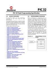
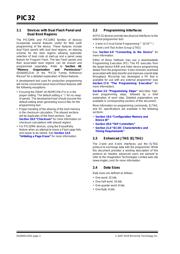
2.1 Devices with Dual Flash Panel and
Dual Boot Regions
The PIC32MK and PIC32MZ families of devices
incorporate several features useful for field (self)
programming of the device. These features include
dual Flash panels with dual boot regions, an aliasing
scheme for the boot regions allowing automatic
selection of boot code at start-up and a panel swap
feature for Program Flash. The two Flash panels and
their associated boot regions can be erased and
programmed separately. Refer to Section 48.
“Memory Organization and Permissions”
(DS60001214) of the “PIC32 Family Reference
Manual” for a detailed explanation of these features.
A development tool used for production programming
will not be concerned about most of these features with
the following exceptions:
• Ensuring the SWAP bit (NVMCON<7>) is in the
proper setting. The default setting is ‘0’ for no swap
of panels. The development tool should assume the
default setting when generating source files for the
programming tool.
• Proper handling of the aliasing of the boot memory
in the checksum calculation. The aliased sections
will be duplicates of the fixed sections. See
Section 18.0 “Checksum” for more information on
checksum calculations with aliased regions
• For PIC32MK devices, using the Erase/Retry
feature when an attempt to erase a Flash page fails
and needs to be retried. See Section 13.0
“Initiating a Page Erase” for more information.
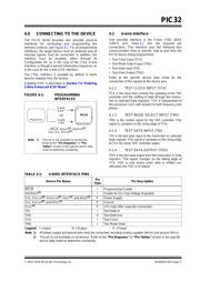
2.2 Programming Interfaces
All PIC32 devices provide two physical interfaces to the
external programmer tool:
• 2-wire In-Circuit Serial Programming™ (ICSP™)
• 4-wire Joint Test Action Group (JTAG)
See Section 4.0 “Connecting to the Device” for
more information.
Either of these methods may use a downloadable
Programming Executive (PE). The PE executes from
the target device RAM and hides device programming
details from the programmer. It also removes overhead
associated with data transfer and improves overall data
throughput. Microchip has developed a PE that is
available for use with any external programmer (see
Section 17.0 “The Programming Executive” for
more information).
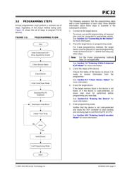
Section 3.0 “Programming Steps” describes high-
level programming steps, followed by a brief
explanation of each step. Detailed explanations are
available in corresponding sections of this document.
More information on programming commands, EJTAG,
and DC specifications are available in the following
sections:
• Section 19.0 “Configuration Memory and
Device ID”
• Section 20.0 “TAP Controllers”
• Section 21.0 “AC/DC Characteristics and
Timing Requirements”
2.3 Enhanced JTAG (EJTAG)
The 2-wire and 4-wire interfaces use the EJTAG
protocol to exchange data with the programmer. While
this document provides a working description of this
protocol as needed, advanced users are advised to
refer to the Imagination Technologies Limited web site
(www.imgtec.com) for more information.
2.4 Data Sizes
Data sizes are defined as follows:
• One word: 32 bits
• One-half word: 16 bits
• One-quarter word: 8 bits
• One Byte: 8 bits
器件 Datasheet 文档搜索
AiEMA 数据库涵盖高达 72,405,303 个元件的数据手册,每天更新 5,000 多个 PDF 文件
