Datasheet 搜索 > 实时时钟芯片 > Maxim Integrated(美信) > DS1337S+C01 数据手册 > DS1337S+C01 开发手册 2/6 页

 器件3D模型
¥ 0
DS1337S+C01 开发手册 - Maxim Integrated(美信)
制造商:
Maxim Integrated(美信)
分类:
实时时钟芯片
封装:
SOIC-8
Pictures:
3D模型
符号图
焊盘图
引脚图
产品图
页面导航:
封装尺寸在P3
技术参数、封装参数在P2
应用领域在P5
型号编号列表在P3
导航目录
DS1337S+C01数据手册
Page:
of 6 Go
若手册格式错乱,请下载阅览PDF原文件
Crystal Parameters
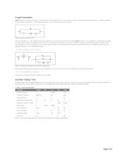
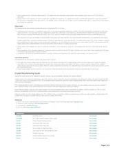
Figure 3 shows the equivalent circuit for a crystal. Near the resonate frequency the circuit consists of a series circuit including motional inductance L
1
, motional resistance
R
1
, and motional capacitance C
1
. The parallel component C
O
is the shunt capacitance of the crystal.
Figure 3. Crystal equivalent circuit.
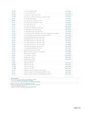
The load capacitance C
L
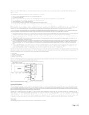
is the capacitive load of the oscillating circuit as seen from the pins of the crystal. Figure 4 shows C
L
as a capacitance in parallel with the crystal.
The load capacitors used in an oscillator circuit, C
L
1 and C
L
2, plus any stray capacitance in the circuit, combine to create the overall load capacitance. All Maxim RTCs
have integrated C
L
1 and C
L
2 capacitors. Care should be taken to minimize stray capacitance in the printed circuit board (PCB) layout. The following formula shows the
relationship between C
L
and load capacitor values:
C
L
= [(C
L
1 × C
L
2)/(C
L
1 + C
L
2) + C
STRAY
]
Figure 4. Crystal load capacitors and equivalent parallel load.
Most crystals allow a maximum drive level of 1µW. All Maxim RTCs run under 1µW. Drive level can determined using the following formula:
P = 2R
1
× [π × 32,768(C
O
+ C
L
)V
RMS
]²
where V
RMS
is the RMS value of the voltage across the crystal.
Oscillator Startup Time
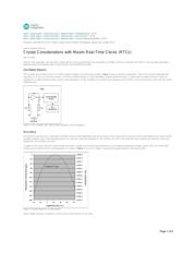
Oscillator startup times are highly dependent upon crystal characteristics, PCB leakage, and layout. High ESR and excessive capacitive loads are the major contributors to
long startup times. A circuit using a crystal with the recommended characteristics and proper layout usually starts within one second.
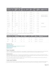
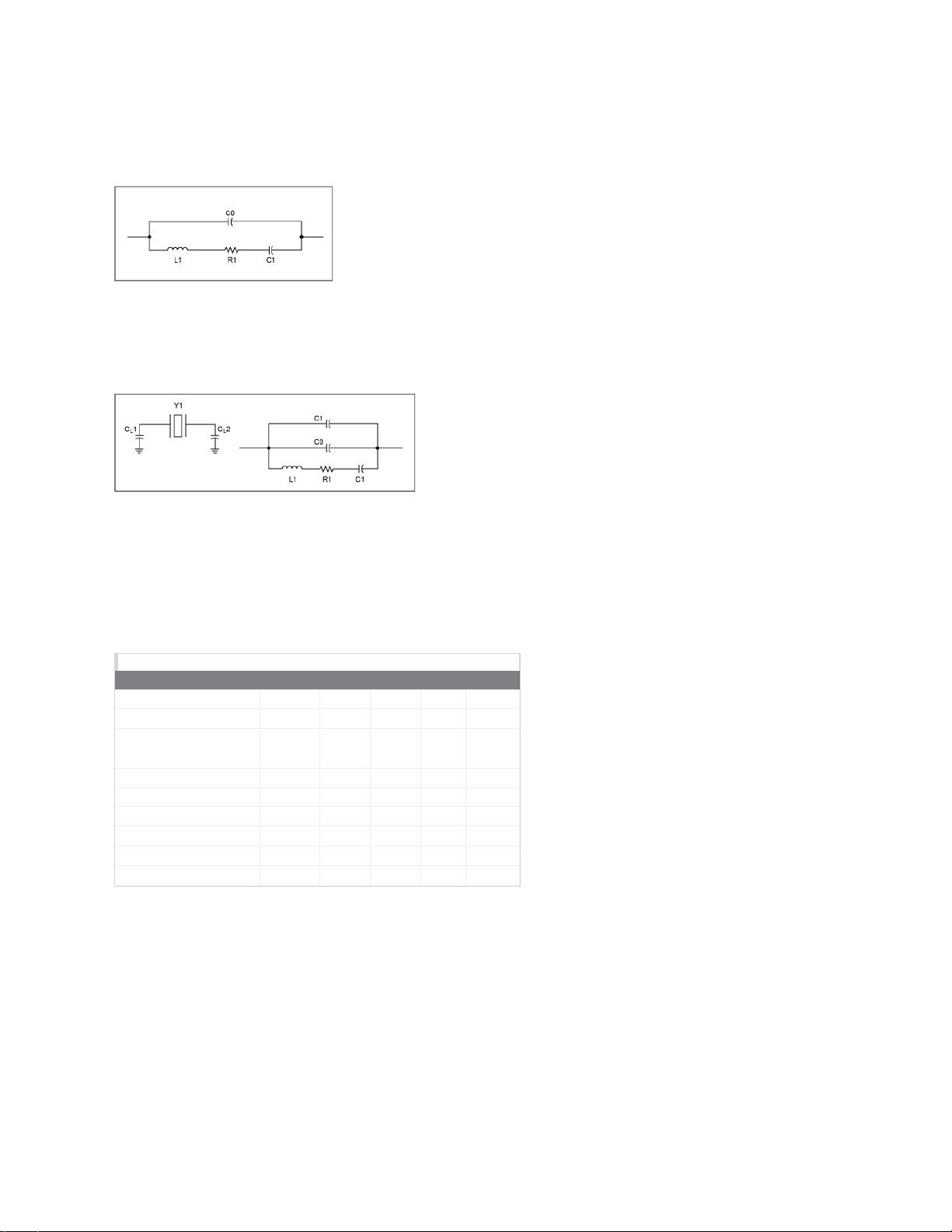
Table 1. Crystal Specifications
Parameter Symbol Min Typ Max Units
Nominal Frequency f
O
32.768 kHz
Frequency Tolerance delta f/f
O
±20 ppm
Load Capacitance C
L
6 pF
Temperature Turnover Point T
0
20 25 30 °C
Parabolic Curvature Constant k
0.042 ppm/°C
Quality Factor Q 40,000 70,000
Series Resistance ESR 45 kΩ
Shunt Capacitance C
0
1.1 1.8 pF
Capacitance Ratio C
0
/C
1
430 600
Drive Level D
L
1 µW
Note 1: Some devices allow higher ESR values, check the datasheet for specific requirements.
Page 2 of 6
器件 Datasheet 文档搜索
AiEMA 数据库涵盖高达 72,405,303 个元件的数据手册,每天更新 5,000 多个 PDF 文件
