Datasheet 搜索 > 实时时钟芯片 > Maxim Integrated(美信) > DS1337S+C01 数据手册 > DS1337S+C01 开发手册 3/6 页

 器件3D模型
¥ 0
DS1337S+C01 开发手册 - Maxim Integrated(美信)
制造商:
Maxim Integrated(美信)
分类:
实时时钟芯片
封装:
SOIC-8
Pictures:
3D模型
符号图
焊盘图
引脚图
产品图
页面导航:
封装尺寸在P3
技术参数、封装参数在P2
应用领域在P5
型号编号列表在P3
导航目录
DS1337S+C01数据手册
Page:
of 6 Go
若手册格式错乱,请下载阅览PDF原文件
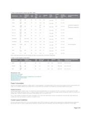
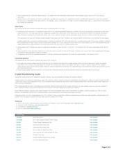
Table 2. Crystal Suppliers, Cylinder-Type (ESR = 45kΩ)
Manufacturer Part
Frequency
Tolerance
(ppm)
ESR
(kΩ)
Drive
Level
max
(µW)
C
L
-
pF
Alternate
C
L
?
Temp
Range
(°C)
Surface
or
Thru-
Hole
Package
Dimensions
(mm)
Manufacturer Ordering
Number
Citizen
CFS-
145
±20 40 1.0 8.0 yes
-
10
to +60
TH 1.5 x 5.1
Citizen
CFS-
206
±20 35 1.0 12.5 yes
-
10
to +60
TH 2.1 x 6.2
Citizen
CMR-
200T
±20 35 1.0
12.5
or
6.0
yes
-
40
to +85
SMT 2.0 X 6.0
CMR200TB32.768KDZFTR
or
CMR200TB32.768KDZBTR
ECS,
Inc.
ECS-
3X8
±20 35 1.0 12.5 ?
-
10
to +60
TH 3.1 x 8.2
ECS, Inc.
ECS-
2X6
±20 35 1.0
12.5 ?
-
10 to +60
TH 2.1 x 6.2
ECS, Inc.
ECS-
1X5
±20 35 1.0
8 ?
-
10
to +60
TH 1.5 x 5.1
KDS/Daiwa
DT-
26
±20 or ±30 40
1.0 12.5 yes
-
10
to +60
TH 2.0 x 6.0 1TB602G00
KDS/Daiwa
DT
-
38
±20 or ±30 30 1.0 12.5 yes
-
10 to +60
TH 3.0 x 8.0
Pletronics WX26 ±20 40 1.0 12.5 6.0
-
10 to +60
TH 2.1 x 6.2 WX26
-32.768k-6pF
Fox
NC-
38
35 1.0 12.5 6.0
-
20 to +60
TH 3.0 x 8.3
Seiko
C-
001R
±20 45 1.0 12.5 6
-
10
to +60
TH 3.1 x 8.0
Seiko C-2 ±20 35 1.0 12.5
6
-
10
to +60
TH 2.0 x 6.0
Note: Cylinder-type
dimensions are barrel diameter and length, and exclude leads. All dimensions approximate.
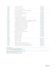
Table 3. Crystal Suppliers, Surface Mount
Manufacturer Part
Frequency
Tolerance (ppm)
ESR
(kΩ)
Drive Level
max (µW)
C
L
-
pF
Alternate
C
L
?
Temp
Range (°C)
Dimensions (mm) approximate,
including leads
Seiko
SP-
T2
±20 50 1.0 12.5 yes -40 to +85 8.7 x 3.7 x 2.5
EPSON
MC-
306
±20 50 1.0 12.5 yes -40 to +85 8.0 x 3.8 x 2.54
KDS
DMX-
26S
±30 50 1.0 12.5 yes -40 to +85 8.0 x 3.8 x 2.4
Manufacturer Links
http://cfm.citizen.co.jp/english/
http://www.eea.epson.com/
http://www.kds.info/html/products/products_catalog/Product List_en.php?id=1
http://www.pletronics.com/XTAL.htm#32
http://www.foxonline.com/
http://www.ecsxtal.com/
Power Consumption
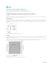
Many RTCs are designed to operate from a battery supply. In a typical application, a small lithium battery can be used to run the oscillator and clock circuitry while the main
supply is off. To maximize battery life, the oscillator must run using as little power as possible. To accomplish this, some design tradeoffs must be made.
Negative Resistance
For typical high-frequency oscillator circuits, it is normal for the circuit to be designed with a 5x or 10x margin for the ESR. Low-frequency crystals typically have higher
ESRs. An RTC oscillator may have less than a 2x margin for negative resistance. An oscillator circuit with a low margin normally consumes less current. As a result, an RTC
oscillator often is sensitive to relatively small amounts of stray leakage, noise, or an increase in ESR.
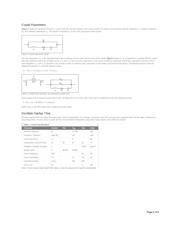
The C
L
of the oscillator circuit influences the power consumption. An RTC with 12.5pF internal loads consumes more power than one that has 6pF loads. However, the
oscillator with 12.5pF load capacitors is usually less susceptible to noise.
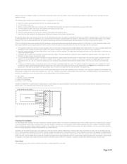
Crystal Layout Guidelines
Since the crystal inputs of Maxim RTCs have very high impedance (about 10
9
Ω), the leads to the crystal act like very good antenna, coupling high-frequency signals from
the rest of the system. If a signal is coupled onto the crystal pins, it can either cancel out or add pulses. Since most of the signals on a board are at a much higher
Page 3 of 6
器件 Datasheet 文档搜索
AiEMA 数据库涵盖高达 72,405,303 个元件的数据手册,每天更新 5,000 多个 PDF 文件
