Datasheet 搜索 > 实时时钟芯片 > Maxim Integrated(美信) > DS1337S+C01 数据手册 > DS1337S+C01 开发手册 5/6 页

 器件3D模型
¥ 0
DS1337S+C01 开发手册 - Maxim Integrated(美信)
制造商:
Maxim Integrated(美信)
分类:
实时时钟芯片
封装:
SOIC-8
Pictures:
3D模型
符号图
焊盘图
引脚图
产品图
页面导航:
封装尺寸在P3
技术参数、封装参数在P2
应用领域在P5
型号编号列表在P3
导航目录
DS1337S+C01数据手册
Page:
of 6 Go
若手册格式错乱,请下载阅览PDF原文件

1. Noise coupling into the crystal from adjacent signals. This problem has been extensively covered above. Noise coupling usually causes an RTC to be grossly
inaccurate.
2. Wrong crystal. An RTC typically runs fast if a crystal with a specified load capacitance (C
L
) greater than the RTC-specified load capacitance is used. The severity of
the inaccuracy is dependent on the value of the C
L
. For example, using a crystal with a C
L
of 12pF on an RTC designed with a 6pF C
L
causes the RTC to be about 3
to 4 minutes per month fast.
Slow Clocks
The following are the most common scenarios that cause a crystal-based RTC to run slow.
1. Overshoots on RTC input pins. It is possible to cause a RTC to run slow by periodically stopping the oscillator. This can be inadvertently accomplished by noisy input
signals to the RTC. If an input signal rises to a voltage that is greater than a diode drop (~0.3V) above V
DD
, the ESD protection diode for the input pin will forward
bias, allowing the substrate to be flooded with current. This, in turn, stops the oscillator until the input signal voltage decreases to below a diode drop above V
DD
.
This mechanism can cause the oscillator to stop frequently if input signals are noisy. Therefore, care should be taken to ensure there is no overshoot on input signals.
Another situation that is common to overshoot problem is having an input to the RTC at 5V when the RTC is in battery-backup mode. This can be a problem in systems
that systematically shut down certain circuits but keep others powered up. It is very important to ensure there are no input signals to the RTC that are greater than the
battery voltage (unless stated otherwise in the device data sheet) when the device is in battery-backup mode.
2. Wrong crystal. A RTC typically runs slow if a crystal with a specified C
L
is less than the C
L
of the RTC. The severity of the inaccuracy is dependent on the value of
the C
L
.
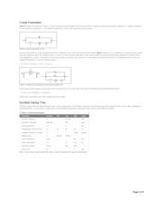
3. Stray capacitance. Stray capacitance between the crystal pins and/or to ground can slow an RTC down. Therefore, care must be taken when designing the PCB layout
to ensure the stray capacitance is kept to a minimum.
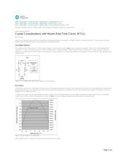
4. Temperature. The further the operating temperature is from the crystal turnover temperature, the slower the crystal oscillates. See Figures 3 and 4.
Clock Does Not Run
The following are the most common scenarios that cause a RTC to not run.
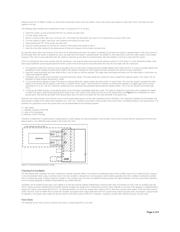
1. The single most common problem when the clock does not run is that the clock halt (CH) or enable oscillator (EOSC) bit has not been set or cleared, as required.
Many Maxim RTCs include a circuit that keeps the oscillator from running when power is first applied. This allows a system to wait for shipment to the customer,
without drawing power from the backup battery. When the system is powered for the first time, the software/firmware must enable the oscillator and prompt the user for
the correct time and date.
2. Surface mount crystals may have some N.C. (no connect) pins. Make sure that the correct pins from the crystal are connected to the X1 and X2 pins.
Crystal Manufacturing Issues
Tuning fork crystals should not be exposed to ultrasonic cleaning. They are susceptible to damage from resonant vibration.
Crystals should not be exposed to temperatures above their maximum ratings. Exposure to excessive temperatures may damage the crystal, and usually increase the ESR.
Crystal "cans" should not be soldered to a PCB. This is sometimes done to ground the case of the crystal. Soldering directly to the case of the crystal usually subjects the
unit to excessive temperatures.
RTCs should generally be used in noncondensing environments. Moisture forming around the oscillator conductors can cause leakage, which can cause the oscillator to
stop. Conformal coatings can be used to protect the circuit, however, conformal coating may by itself cause problems.
Some conformal coatings, especially epoxy-based materials, can have unacceptable levels of ionic contamination. In addition, conformal coatings can, if the PC board
surface is not sufficiently cleaned prior to conformal coating, cause contaminants to concentrate around leads and traces.
Solder flux residue can cause leakage between pins. RTC oscillator circuits are especially sensitive to leakage because of their low-power operation. Leakage between the
oscillator input and output, or leakage to ground, often keep the oscillator from running.
References
1. John R. Vig, Quartz Crystal Resonators and Oscillators for Frequency Control and Timing Applications, www.rakon.com/
2.
Advanced Crystal Technology, www.actcrystals.com/act/
3. Fox Electronics, www.foxonline.com/
4. ECS, Inc. International, www.ecsxtal.com/
Related Parts
DS12885 Real-Time Clocks Free Samples
DS12R885 RTCs with Constant-Voltage
Trickle Charger Free Samples
DS1302 Trickle-Charge Timekeeping Chip Free
Samples
DS1305 Serial Alarm Real-Time Clock Free Samples
DS1306 Serial Alarm Real-Time
Clock Free Samples
DS1307 64 x 8, Serial, I²C
Real-Time Clock Free Samples
DS1308 Low-Current I²C RTC
with 56-Byte NV RAM Free Samples
DS1315 Phantom Time Chip Free Samples
DS1318 Parallel-Interface Elapsed Time
Counter Free Samples
DS1337 I²C Serial Real-Time
Clock Free Samples
Page 5 of 6
器件 Datasheet 文档搜索
AiEMA 数据库涵盖高达 72,405,303 个元件的数据手册,每天更新 5,000 多个 PDF 文件
